


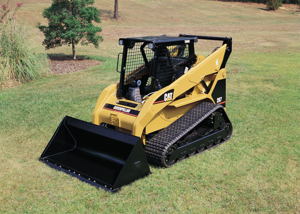
Caterpillar Caterpillar Backhoe Loader 420D 420D
Need answers fast?
Explore the manual using AI.
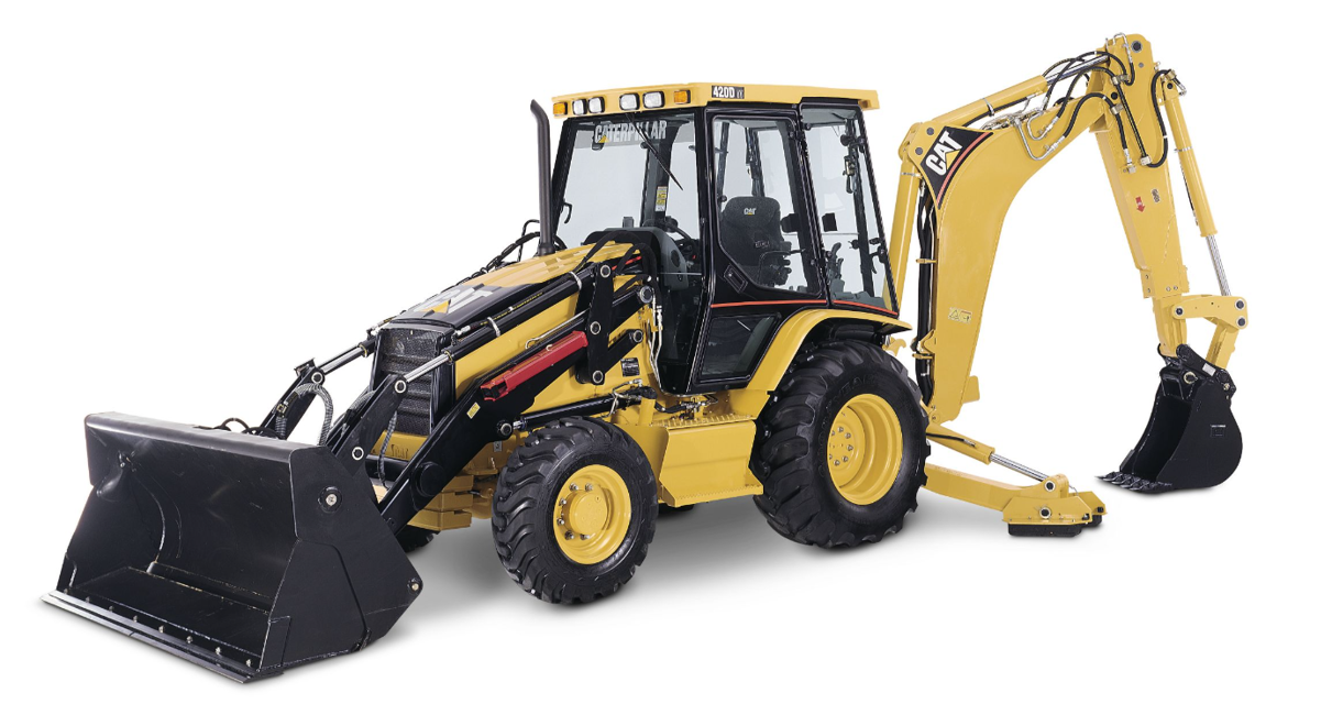
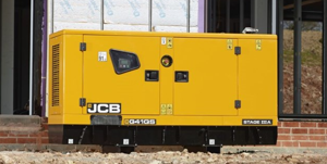
The Caterpillar Backhoe Loader 420D is a versatile and powerful machine designed for construction and excavation tasks. Known for its durability and efficiency, this model combines advanced hydraulic systems with robust performance, making it an essential asset for any heavy equipment fleet.
Turn manuals into instant answers
with your AI-powered assistantTurn manuals into instant answers
with your AI-powered assistant
Manual for Caterpillar Caterpillar Backhoe Loader 420D 420D
Complete asset maintenance, one click away
Get instant access to all the maintenance information you need. Empower technicians to perform preventive maintenance with asset packages, ready to use right out of the box.

Documents & Manuals
Find all the essential guides in one place.
 Tensioning Guide
- Belt-diagram
- C-120 pulleys
+ 13 more

Work Order Templates
Pre-built workflows to keep your asset running smoothly.
- Daily Electrical System Inspection
- Replace Roller and Pulley
- Install Engine B-120
+ 29 more

Procedures
Integrate maintenance plans directly into your work orders.
- Motion Industries
- Applied Industrial Technologies
- Electrical Brothers
+ 5 more

Parts
Access the parts list for your equipment in MaintainX.
- Drive Motor
- B2 Rollers
- Tensioning System
+ 40 more
Caterpillar Caterpillar Backhoe Loader 420D 420D
Create an account to install this asset package.
Maintenance Plans for Caterpillar Caterpillar Backhoe Loader 420D Model 420D
Integrate maintenance plans directly into your work orders in MaintainX.
Idler Gear Installation
NOTICE: Keep all parts clean from contaminants. Contaminants may cause rapid wear and shortened component life.
Use Tooling (A) to ensure that the No. 1 cylinder is at the top center compression stroke.
NOTICE: The valve timing and the fuel injection pump timing will be lost if the crankshaft is rotated when the idler gear is removed.
Position idler gear hub (9) and install bolts (7) in order to locate the idler gear hub.
Use a suitable press and Tooling (E) to install bushings (8) on each side of idler gear (5).
Remove bolts (7) from the idler gear hub. Install idler gear (5) on idler gear hub (9).
Install retainer plate (6) and bolts (7).
Check the end play for the idler gear.
Check the backlash between the idler gear and the camshaft gear.

Idler Gear Removal
Start By:
a. Remove the crankshaft pulley. Refer to Disassembly and Assembly, 'Crankshaft Pulley - Remove and Install'.
b. Remove the front cover. Refer to Disassembly and Assembly, 'Front Cover - Remove and Install'.
NOTICE: Keep all parts clean from contaminants. Contaminants may cause rapid wear and shortened component life.
NOTICE: Care must be taken to ensure that fluids are contained during performance of inspection, maintenance, testing, adjusting, and repair of the product. Be prepared to collect the fluid with suitable containers before opening any compartment or disassembling any component containing fluids.
Refer to Special Publication, NENG2500, 'Dealer Service Tool Catalog' for tools and supplies suitable to collect and contain fluids on Cat products.
Dispose of all fluids according to local regulations and mandates.
1. Use Tooling (A) to ensure that the No. 1 cylinder is at the top center compression stroke. Refer to Testing and Adjusting, 'Finding Top Center Position for No. 1 Piston'.
Note: Install Tooling (B) through the camshaft gear. Install Tooling (C) into the crankshaft web.
Accessory Drive Removal
NOTICE: Keep all parts clean from contaminants. Contaminants may cause rapid wear and shortened component life.
Remove the front cover (7). Refer to this Disassembly and Assembly Manual, 'Front Cover - Remove and Install'.
Remove the Allen head screws (2) and (9). Remove the accessory drive assembly (8) from the rear face of the front housing (11).
Remove circlip (6) from housing (8).
Use the Tooling (A) in order to remove the bearings (3) and (4) from the gear and the housing.
Remove the O-ring (12) from the front housing (8) and discard the O-ring.
Sign off on the accessory drive removal
Housing Front Installation
NOTICE:
Keep all parts clean from contaminants.
Contaminants may cause rapid wear and shortened component life.
1. Clean all mating surfaces thoroughly.
2. Ensure that thrust washer (10) is aligned with hollow dowel (12). Install the thrust washer on camshaft (11).
3. Install a new O-ring seal on the fuel injection pump housing.
4. Install Tooling (A) in the cylinder block in Hole (Y).
5. Position gasket (8) on Tooling (A). Install gasket (6) on the back side of front housing (5).
6. Position front housing (5) on the cylinder block. Install bolts (7) and bolts (9). Remove Tooling (A) and install the remaining bolts in order to secure the front housing to the cylinder block. Tighten bolts (7) and bolts (9) finger tight at this time.
Accessory Drive Installation
NOTICE: Keep all parts clean from contaminants. Contaminants may cause rapid wear and shortened component life.
Inspect the condition of the teeth and the splines of the gear (5), the bearings (3 and 4), the circlip (6), and the groove for the circlip in the front housing (8) for wear and for damage. Replace any worn component or any damaged component.
Apply a small continuous bead of the Tooling (B) to the outer surface of the bearing (4). Support the front face of the housing (8). Position the bearing in the housing. Use a suitable adapter on the outer race of the bearing and press the bearing into the housing (8) until the bearing is against the front face of the recess. Remove any excess bearing mount compound.
Apply a small continuous bead of the Tooling (B) to the inner surface of the bearing (4). Support the bearing (4). Position the small hub of the gear (5) toward the bearing and press the gear (5) into the bearing until the shoulder of the gear is against the bearing. Remove any excess bearing mount compound.
Apply a small continuous bead of the Tooling (B) to the inner surface and the outer surface of the bearing (3). Support the bearing (4). Use a suitable adapter on the outer race of the bearing (3) and press the bearing into the housing and onto the shoulder of the gear. Remove any excess bearing mount compound.
Install the circlip (6) into the groove in the front housing (8). Install a new O-ring seal (12) on housing (8).
Lubricate the O-ring seal with red rubber grease and install the housing in front housing (11). Install Allen head screws (2) and (9) to secure housing (8) in the front housing.
Check the backlash between the idler gear and gear (5). The backlash for the gears is 0.11 to 0.17 mm (0.004 to 0.007 inch).
Install the front cover (7) on the front housing. Refer to this Disassembly and Assembly Manual, 'Front Cover - Remove and Install'.
Parts for Caterpillar Caterpillar Backhoe Loader 420D 420D
Access the parts list for your equipment in MaintainX.
Crankshaft Turning Tool
9U-6198
Screw
5F-7345
Driver Group
1P-0510
Timing Pin (Crankshaft)
230-6283
Sliding Plate
126-7181
Crankshaft Turning Tool
9U-6198
Screw
5F-7345
Driver Group
1P-0510
Timing Pin (Crankshaft)
230-6283
Sliding Plate
126-7181
Crankshaft Turning Tool
9U-6198
Screw
5F-7345
Driver Group
1P-0510
Timing Pin (Crankshaft)
230-6283
Sliding Plate
126-7181
Unlock efficiency
with MaintainX CoPilot
MaintainX CoPilot is your expert colleague, on call 24/7, helping your team find the answers they need to keep equipment running.
Reduce Unplanned Downtime
Ensure your team follows consistent procedures to minimize equipment failures and costly delays.
Maximize Asset Availability
Keep your assets running longer and more reliably, with standardized maintenance workflows from OEM manuals.
Lower Maintenance Costs
Turn any technician into an expert to streamline operations, maintain more assets, and reduce overall costs.
Thousands of companies manage their assets with MaintainX

'%3e%3cpath%20fill='url(%23b)'%20d='M66.008%2080.068c-5.084-.786-9.763-3.834-12.442-8.68a16.942%2016.942%200%200%201-1.87-5.18c1.096.19%202.203.476%203.298.87%206.525%202.333%2010.836%207.68%2011.014%2012.99ZM51.47%2061.576c.488-5.524%203.62-10.716%208.847-13.597a17.132%2017.132%200%200%201%2011.335-1.882c-.798%208.145-7.43%2014.848-16.038%2015.599-1.417.119-2.799.07-4.144-.12Zm28.564-11.478a17.513%2017.513%200%200%201%203.727%204.62c4.608%208.335%201.584%2018.813-6.75%2023.409a16.988%2016.988%200%200%201-4.359%201.679%2019.624%2019.624%200%200%201-3.977-12.776c.346-7.561%204.942-13.931%2011.36-16.932Z'/%3e%3cpath%20fill='%23110F0D'%20fill-rule='evenodd'%20d='M142.831%2048.324h4.977V77.03h-4.977V48.324Zm27.278%2013.002c.322%201.048.453%202.263.453%203.62v12.073h-4.787V66.208c0-.75-.047-1.572-.154-2.143-.453-2.382-1.822-3.572-4.215-3.572-2.31%200-3.882%201.274-4.43%203.476-.143.596-.226%201.405-.226%202.25v10.8h-4.787V56.623h4.477v2.989c1.536-2.5%203.906-3.43%206.371-3.43%203.488%200%206.263%201.68%207.298%205.144Zm24.636%207.323c0%203.882-2.358%206.525-5.763%207.727-1.298.453-2.632.643-4.62.643h-10.169V48.324h9.085c1.691%200%203.156.143%204.049.38%203.465.93%205.727%203.68%205.727%207.335%200%202.441-.81%204.156-2.762%205.644%202.905%201.417%204.453%203.727%204.453%206.966Zm-15.634-8.656h4.584c1.024%200%201.917-.143%202.536-.417%201.215-.548%201.905-1.608%201.905-3.167%200-1.548-.643-2.572-1.845-3.132-.691-.31-1.762-.452-2.763-.452h-4.417v7.168Zm10.716%208.465c0-1.536-.893-3.37-3.227-3.893-.428-.095-1.036-.143-1.571-.143h-5.918v8.085h5.501c.56%200%201.429-.048%201.953-.167%201.94-.453%203.262-1.846%203.262-3.882Zm47.747-11.847-8.097%2020.408h-4.429l-8.109-20.408h5.191l5.192%2014.574%205.108-14.574h5.144Zm-20.218%2010.002c0%20.69-.036%201.262-.155%201.94h-15.943c.631%202.87%202.714%204.728%205.882%204.728%202.131%200%203.607-.882%204.703-2.525h4.87c-1.762%204.144-5.204%206.692-9.657%206.692-6.084%200-10.537-4.858-10.537-10.49%200-6.108%204.524-10.776%2010.335-10.776%206.239%200%2010.442%204.954%2010.502%2010.43Zm-4.763-1.405c-.333-2.846-2.643-4.858-5.691-4.858-2.894%200-5.287%201.929-5.621%204.858h11.312Zm-72.667%203.44c0%204.787-3.287%208.371-9.419%208.371H119.363V64.66c-1.917.274-3.87.69-5.811%201.238l4.537%2011.121h-5.418l-3.596-9.585c-5.144%202.084-10.085%205.216-14.217%209.585h-4.786L101.8%2048.312h4.56l5.68%2013.883a44.112%2044.112%200%200%201%207.323-1.774V48.312h9.084c1.703%200%203.156.143%204.061.393%203.453.929%205.727%203.667%205.727%207.323%200%201.917-.738%204.179-2.81%205.691%203.06%201.56%204.501%204.025%204.501%206.93Zm-15.634-8.667a62.664%2062.664%200%200%201%202.06-.036c1.703.012%203.239.131%204.608.37%201.441-.549%202.357-1.727%202.357-3.537%200-1.941-.881-3.144-2.488-3.667-.548-.18-1.358-.286-2.322-.286h-4.215v7.156Zm-16.55%203.905-3.715-9.894-6.394%2016.502c2.833-2.595%206.263-4.858%2010.109-6.608Zm27.254%204.74c0-2.775-3.131-4.347-8.513-4.418-.715%200-1.441.011-2.191.047v8.252h5.918c2.548%200%204.786-1.37%204.786-3.882Z'%20clip-rule='evenodd'/%3e%3c/g%3e%3cdefs%3e%3clinearGradient%20id='b'%20x1='51.47'%20x2='85.916'%20y1='62.946'%20y2='62.946'%20gradientUnits='userSpaceOnUse'%3e%3cstop%20stop-color='%23CD9F28'/%3e%3cstop%20offset='1'%20stop-color='%23ECD80B'/%3e%3c/linearGradient%3e%3cclipPath%20id='a'%3e%3cpath%20fill='%23fff'%20d='M51.47%2045.728h186.104V80.14H51.47z'/%3e%3c/clipPath%3e%3c/defs%3e%3c/svg%3e)


More from Caterpillar


Explore Other Assets


© 2025 MaintainX. All rights reserved.