


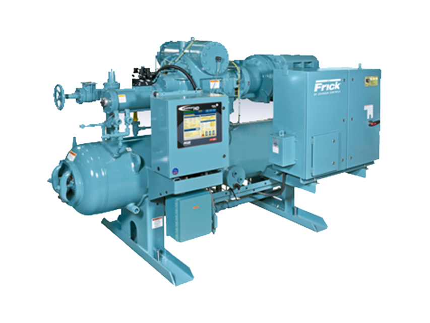
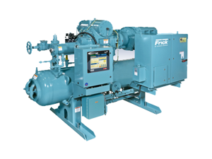
Frick Rotary Screw Compressor RWF II 856
Need answers fast?
Explore the manual using AI.
Turn manuals into instant answers
with your AI-powered assistantTurn manuals into instant answers
with your AI-powered assistant
Manual for Frick Rotary Screw Compressor RWF II 856
Complete asset maintenance, one click away
Get instant access to all the maintenance information you need. Empower technicians to perform preventive maintenance with asset packages, ready to use right out of the box.

Documents & Manuals
Find all the essential guides in one place.
 Tensioning Guide
- Belt-diagram
- C-120 pulleys
+ 13 more

Work Order Templates
Pre-built workflows to keep your asset running smoothly.
- Daily Electrical System Inspection
- Replace Roller and Pulley
- Install Engine B-120
+ 29 more

Procedures
Integrate maintenance plans directly into your work orders.
- Motion Industries
- Applied Industrial Technologies
- Electrical Brothers
+ 5 more

Parts
Access the parts list for your equipment in MaintainX.
- Drive Motor
- B2 Rollers
- Tensioning System
+ 40 more
Frick Rotary Screw Compressor RWF II 856
Create an account to install this asset package.
Maintenance Plans for Frick Rotary Screw Compressor Model RWF II 856
Integrate maintenance plans directly into your work orders in MaintainX.
Oil Change
WARNING: Do not mix oils of different brands, manufacturers, or types. Mixing of oils may cause excessive oil foaming, nuisance oil level cutouts, oil pressure loss, gas or oil leakage and catastrophic compressor failure.
Shut down the unit when changing oil. At the same time all oil filter cartridges must be changed and all oil strainer elements removed and cleaned.
Press the [STOP] key on the microprocessor panel to stop the compressor unit.
Open the disconnect switch for the compressor motor starter.
Close the suction and discharge service valves; also close the liquid-injection and economizer service valves, if applicable.
Slowly vent separator to low-side system pressure using the bypass line on the suction trap.
NOTICE: Recover or transfer all refrigerant vapor, in accordance with local ordinances, before opening to atmosphere. The separator must be equalized to atmospheric pressure.
WARNING: Oil-entrained refrigerant may vaporize, causing a separator pressure increase. Repeat venting and recovery procedure, if necessary.
Open the drain valve(s) located on the underside of the separator and drain the oil.

5000 Hourly Rotary Screw Compressor Check
Check alignment (h)
Refer to 070.210-IB for foot mounting alignment.
Check electrical connections (b)
Check and torque all terminals in the processor and starter panel per the specification posted in the enclosure.
Sign off on the 5000 Hourly Rotary Screw Compressor Check
Temperature Sensor Replacement
WARNING: Be extremely careful not to loosen thermowell while attempting to remove the temperature sensor. The use of two wrenches will be necessary to ensure the thermowell remains stationary. Loss of oil and/or refrigerant could occur. Exposure to refrigerant fumes and/or hot oil can cause injury or death.
Control power shut off
Upload a photo of the DIN connector plug removed from transmitter
Transmitter unit removed
Thermal compound applied to new sensor assembly
New sensor assembly inserted into thermal well and knurled ring tightened
Upload a photo of the DIN connector plug applied to transmitter
Control power turned on
NOTICE: The temperature sensor is factory set. If calibration is required, refer to Calibration Instructions in publication 090.040-O for service technicians.
Oil Level Transmitter Replacement
The Oil Level Transmitter is located on the front of the separator near the bottom/center. See Figure 52.
The linear transmitter with hermetic enclosure is based on the capacitive measuring principle.
It features removable electronics (from the sensor well) eliminating the need to evacuate the compressor for replacement. This transmitter is dedicated to oil level control and has no user adjustments.
Shut off control power.
Remove DIN connector plug from transmitter.
Loosen set screws.
Remove transmitter unit.
Install new transmitter unit.
Tighten set screws.
Pressure Transducer Replacement
Warning: Follow all safety guidelines and procedures during the replacement process.
Control power shut off
Applicable transducer isolation valve closed
NOTICE: To change the discharge pressure transducer (PE-3), it will be necessary to depressurize the entire compressor package. Follow 'General Instructions For Replacing Compressor Unit Components' before going to step 3.
Wiring harness connectors identified
Wiring harness connector disconnected from transducer
Transducer unscrewed using a wrench on the metal hex at the base of the transducer
New transducer installed
Wiring harness reconnected to the transducer
Parts for Frick Rotary Screw Compressor RWF II 856
Access the parts list for your equipment in MaintainX.
Rotary Screw Compressor
US2430129999900010
Frick Optical Isolation Kits
639C0133G01
Oil Analysis Kit
333Q0001853
Rotary Screw Compressor
US2430129999900010
Frick Optical Isolation Kits
639C0133G01
Oil Analysis Kit
333Q0001853
Rotary Screw Compressor
US2430129999900010
Frick Optical Isolation Kits
639C0133G01
Oil Analysis Kit
333Q0001853
Unlock efficiency
with MaintainX CoPilot
MaintainX CoPilot is your expert colleague, on call 24/7, helping your team find the answers they need to keep equipment running.
Reduce Unplanned Downtime
Ensure your team follows consistent procedures to minimize equipment failures and costly delays.
Maximize Asset Availability
Keep your assets running longer and more reliably, with standardized maintenance workflows from OEM manuals.
Lower Maintenance Costs
Turn any technician into an expert to streamline operations, maintain more assets, and reduce overall costs.
Thousands of companies manage their assets with MaintainX

'%3e%3cpath%20fill='url(%23b)'%20d='M66.008%2080.068c-5.084-.786-9.763-3.834-12.442-8.68a16.942%2016.942%200%200%201-1.87-5.18c1.096.19%202.203.476%203.298.87%206.525%202.333%2010.836%207.68%2011.014%2012.99ZM51.47%2061.576c.488-5.524%203.62-10.716%208.847-13.597a17.132%2017.132%200%200%201%2011.335-1.882c-.798%208.145-7.43%2014.848-16.038%2015.599-1.417.119-2.799.07-4.144-.12Zm28.564-11.478a17.513%2017.513%200%200%201%203.727%204.62c4.608%208.335%201.584%2018.813-6.75%2023.409a16.988%2016.988%200%200%201-4.359%201.679%2019.624%2019.624%200%200%201-3.977-12.776c.346-7.561%204.942-13.931%2011.36-16.932Z'/%3e%3cpath%20fill='%23110F0D'%20fill-rule='evenodd'%20d='M142.831%2048.324h4.977V77.03h-4.977V48.324Zm27.278%2013.002c.322%201.048.453%202.263.453%203.62v12.073h-4.787V66.208c0-.75-.047-1.572-.154-2.143-.453-2.382-1.822-3.572-4.215-3.572-2.31%200-3.882%201.274-4.43%203.476-.143.596-.226%201.405-.226%202.25v10.8h-4.787V56.623h4.477v2.989c1.536-2.5%203.906-3.43%206.371-3.43%203.488%200%206.263%201.68%207.298%205.144Zm24.636%207.323c0%203.882-2.358%206.525-5.763%207.727-1.298.453-2.632.643-4.62.643h-10.169V48.324h9.085c1.691%200%203.156.143%204.049.38%203.465.93%205.727%203.68%205.727%207.335%200%202.441-.81%204.156-2.762%205.644%202.905%201.417%204.453%203.727%204.453%206.966Zm-15.634-8.656h4.584c1.024%200%201.917-.143%202.536-.417%201.215-.548%201.905-1.608%201.905-3.167%200-1.548-.643-2.572-1.845-3.132-.691-.31-1.762-.452-2.763-.452h-4.417v7.168Zm10.716%208.465c0-1.536-.893-3.37-3.227-3.893-.428-.095-1.036-.143-1.571-.143h-5.918v8.085h5.501c.56%200%201.429-.048%201.953-.167%201.94-.453%203.262-1.846%203.262-3.882Zm47.747-11.847-8.097%2020.408h-4.429l-8.109-20.408h5.191l5.192%2014.574%205.108-14.574h5.144Zm-20.218%2010.002c0%20.69-.036%201.262-.155%201.94h-15.943c.631%202.87%202.714%204.728%205.882%204.728%202.131%200%203.607-.882%204.703-2.525h4.87c-1.762%204.144-5.204%206.692-9.657%206.692-6.084%200-10.537-4.858-10.537-10.49%200-6.108%204.524-10.776%2010.335-10.776%206.239%200%2010.442%204.954%2010.502%2010.43Zm-4.763-1.405c-.333-2.846-2.643-4.858-5.691-4.858-2.894%200-5.287%201.929-5.621%204.858h11.312Zm-72.667%203.44c0%204.787-3.287%208.371-9.419%208.371H119.363V64.66c-1.917.274-3.87.69-5.811%201.238l4.537%2011.121h-5.418l-3.596-9.585c-5.144%202.084-10.085%205.216-14.217%209.585h-4.786L101.8%2048.312h4.56l5.68%2013.883a44.112%2044.112%200%200%201%207.323-1.774V48.312h9.084c1.703%200%203.156.143%204.061.393%203.453.929%205.727%203.667%205.727%207.323%200%201.917-.738%204.179-2.81%205.691%203.06%201.56%204.501%204.025%204.501%206.93Zm-15.634-8.667a62.664%2062.664%200%200%201%202.06-.036c1.703.012%203.239.131%204.608.37%201.441-.549%202.357-1.727%202.357-3.537%200-1.941-.881-3.144-2.488-3.667-.548-.18-1.358-.286-2.322-.286h-4.215v7.156Zm-16.55%203.905-3.715-9.894-6.394%2016.502c2.833-2.595%206.263-4.858%2010.109-6.608Zm27.254%204.74c0-2.775-3.131-4.347-8.513-4.418-.715%200-1.441.011-2.191.047v8.252h5.918c2.548%200%204.786-1.37%204.786-3.882Z'%20clip-rule='evenodd'/%3e%3c/g%3e%3cdefs%3e%3clinearGradient%20id='b'%20x1='51.47'%20x2='85.916'%20y1='62.946'%20y2='62.946'%20gradientUnits='userSpaceOnUse'%3e%3cstop%20stop-color='%23CD9F28'/%3e%3cstop%20offset='1'%20stop-color='%23ECD80B'/%3e%3c/linearGradient%3e%3cclipPath%20id='a'%3e%3cpath%20fill='%23fff'%20d='M51.47%2045.728h186.104V80.14H51.47z'/%3e%3c/clipPath%3e%3c/defs%3e%3c/svg%3e)


More from Frick


Explore Other Assets


© 2026 MaintainX. All rights reserved.