


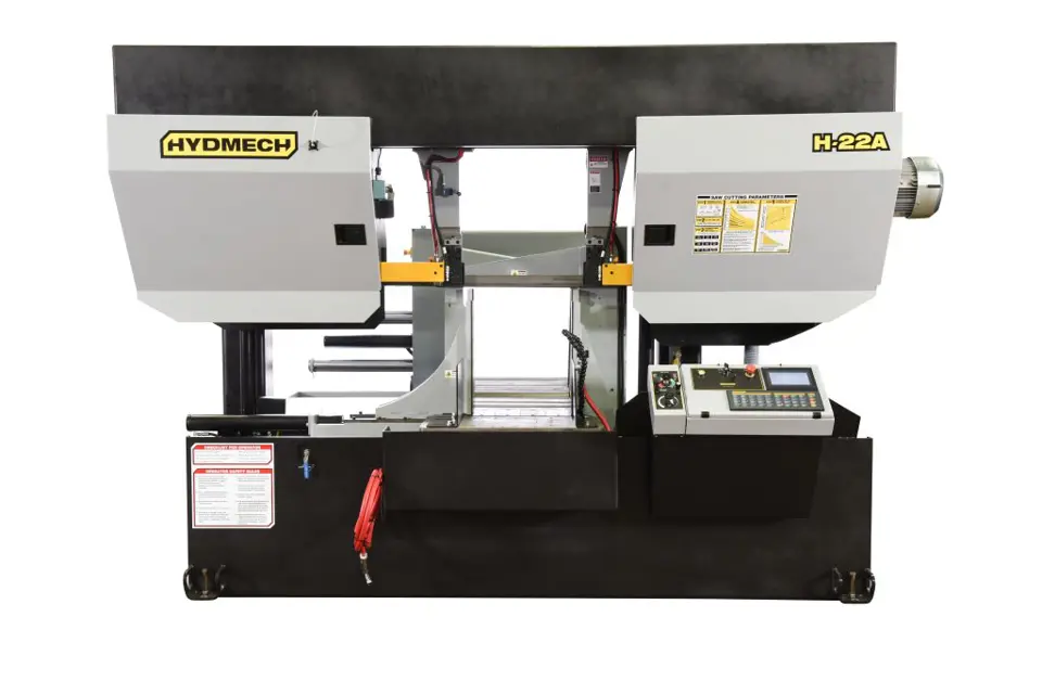
Hyd‑Mech Group Bandsaw H-22A
Need answers fast?
Explore the manual using AI.
Turn manuals into instant answers
with your AI-powered assistantTurn manuals into instant answers
with your AI-powered assistant
Manual for Hyd‑Mech Group Bandsaw H-22A
Complete asset maintenance, one click away
Get instant access to all the maintenance information you need. Empower technicians to perform preventive maintenance with asset packages, ready to use right out of the box.

Documents & Manuals
Find all the essential guides in one place.
 Tensioning Guide
- Belt-diagram
- C-120 pulleys
+ 13 more

Work Order Templates
Pre-built workflows to keep your asset running smoothly.
- Daily Electrical System Inspection
- Replace Roller and Pulley
- Install Engine B-120
+ 29 more

Procedures
Integrate maintenance plans directly into your work orders.
- Motion Industries
- Applied Industrial Technologies
- Electrical Brothers
+ 5 more

Parts
Access the parts list for your equipment in MaintainX.
- Drive Motor
- B2 Rollers
- Tensioning System
+ 40 more
Hyd‑Mech Group Bandsaw H-22A
Create an account to install this asset package.
Maintenance Plans for Hyd‑Mech Group Bandsaw Model H-22A
Integrate maintenance plans directly into your work orders in MaintainX.
500 Hourly Oil Filter Replacement
Warning: Only trained personnel should perform this operation
Enter the machine's hour meter reading
Select the replacement filter used
Was the filter replacement successful?
Sign off on the filter replacement

Blade Guides Adjustment
Warning: This procedure requires trained personnel with PPE!
Are both sets of blade guides identical?
To adjust the carbides, follow the steps below:
Loosen the set screws in the handle bases and remove the handles
Under the handles, are there large hubs with a flat on each side and a socket head cap screw inside the center?
Are the screws holding the carbide pads in place?
Adjust the position of the carbide pads by turning the hubs clockwise to tighten the pads on the blade
Are the hubs tightened against the blade, backed off 1/16 to 1/8 of a turn?
Is the handle installed in the LOCKED position and the set screws tightened?
Blade Tracking Adjustment
IDLER WHEEL TRACKING
Release blade tension before adjusting
Adjust tracking by regulating 'push' set screws and 'pull' bolts
Loosening bolts 'A' and turning in setscrews 'C' by equal amounts will move the blade OFF the wheel
Loosening bolts 'B' and turning in sets crews 'D' by equal amounts will move the blade ON to the wheel
After each 'C' or 'D' set screw adjustment, tighten bolts 'A' or 'B', turn tension switch to '+RUN', run the blade for a moment and recheck the tracking
DRIVE WHEEL TRACKING
Release blade tension before adjusting
Loosening bolts 'A' and turning in set screws 'C' by equal amounts will move the blade OFF the wheel
Blade Replacement
NOTE: Wear gloves, safety glasses and a long sleeve shirt for protection from the sharp blade. The hydraulics should be OFF any time the operator has his/her hands in contact with the blade.
Select MANUAL mode and raise the head so the drive door will clear the electrical control panel.
Release the blade tension by turning the Blade Tension Switch to '-'.
Remove the blade guard.
Shut the machine off and open the idler and drive doors.
Loosen the carbide locking levers by turning counter clockwise 1/4 turn.
At the top of the head, the saw blade runs in a protective channel. Grip the blade at each end of this channel and twist the blade teeth down past the channel and slide the blade forward. Let the blade rest on the out feed table, then slide the blade down and out of the carbide guides.
Before installing the new blade, check that it measures 1.615' wide including the teeth. Some blade manufacturers supply blades that measure 1.5' including the teeth. The same applies to 2' blades, they should measure 2.120'. In this case you may not be able to adjust the head down limit to complete the cut.
Your new blade will be in a coil. While wearing gloves, hold the blade away from yourself, twist the blade to uncoil it. Do not let the blade teeth bounce on the concrete floor as some damage to the blade may be caused.
Hydraulic Maintenance
Warning: This maintenance check requires trained personnel with PPE!
Oil level in the gauge
Type of hydraulic oil used
Oil change procedure followed correctly?
Hydraulic tank capacity in liters
Oil temperature in Celsius
Oil pressure in kPa
Blade tension checked and adjusted if necessary?
Sign off on the hydraulic maintenance
Parts for Hyd‑Mech Group Bandsaw H-22A
Access the parts list for your equipment in MaintainX.
1PB-Emergency Stop Push Button, Red Mushroom Head, Latching Push Button (Telemecanique)
ZB2 BT4
1PB-Emergency Stop Push Button, Mounting Base With 1 N/C Contact Block (Telemecanique)
ZB2 BZ102
2PB-Hydraulic Start Push Button, Green, Illuminated, Flush Head Push Button (Telemecanique)
ZB2 BW33
2PB-Hydraulic Start Push Button, Light Module With 1 N/O Contact Block And 130V (BA9S) Light Bulb (Telemecanique)
ZB2 BW061
2PB-Hydraulic Start Push Button, 130V (BA9S) Light Bulb (Spectro)
SP105
Unlock efficiency
with MaintainX CoPilot
MaintainX CoPilot is your expert colleague, on call 24/7, helping your team find the answers they need to keep equipment running.
Reduce Unplanned Downtime
Ensure your team follows consistent procedures to minimize equipment failures and costly delays.
Maximize Asset Availability
Keep your assets running longer and more reliably, with standardized maintenance workflows from OEM manuals.
Lower Maintenance Costs
Turn any technician into an expert to streamline operations, maintain more assets, and reduce overall costs.
Thousands of companies manage their assets with MaintainX

'%3e%3cpath%20fill='url(%23b)'%20d='M66.008%2080.068c-5.084-.786-9.763-3.834-12.442-8.68a16.942%2016.942%200%200%201-1.87-5.18c1.096.19%202.203.476%203.298.87%206.525%202.333%2010.836%207.68%2011.014%2012.99ZM51.47%2061.576c.488-5.524%203.62-10.716%208.847-13.597a17.132%2017.132%200%200%201%2011.335-1.882c-.798%208.145-7.43%2014.848-16.038%2015.599-1.417.119-2.799.07-4.144-.12Zm28.564-11.478a17.513%2017.513%200%200%201%203.727%204.62c4.608%208.335%201.584%2018.813-6.75%2023.409a16.988%2016.988%200%200%201-4.359%201.679%2019.624%2019.624%200%200%201-3.977-12.776c.346-7.561%204.942-13.931%2011.36-16.932Z'/%3e%3cpath%20fill='%23110F0D'%20fill-rule='evenodd'%20d='M142.831%2048.324h4.977V77.03h-4.977V48.324Zm27.278%2013.002c.322%201.048.453%202.263.453%203.62v12.073h-4.787V66.208c0-.75-.047-1.572-.154-2.143-.453-2.382-1.822-3.572-4.215-3.572-2.31%200-3.882%201.274-4.43%203.476-.143.596-.226%201.405-.226%202.25v10.8h-4.787V56.623h4.477v2.989c1.536-2.5%203.906-3.43%206.371-3.43%203.488%200%206.263%201.68%207.298%205.144Zm24.636%207.323c0%203.882-2.358%206.525-5.763%207.727-1.298.453-2.632.643-4.62.643h-10.169V48.324h9.085c1.691%200%203.156.143%204.049.38%203.465.93%205.727%203.68%205.727%207.335%200%202.441-.81%204.156-2.762%205.644%202.905%201.417%204.453%203.727%204.453%206.966Zm-15.634-8.656h4.584c1.024%200%201.917-.143%202.536-.417%201.215-.548%201.905-1.608%201.905-3.167%200-1.548-.643-2.572-1.845-3.132-.691-.31-1.762-.452-2.763-.452h-4.417v7.168Zm10.716%208.465c0-1.536-.893-3.37-3.227-3.893-.428-.095-1.036-.143-1.571-.143h-5.918v8.085h5.501c.56%200%201.429-.048%201.953-.167%201.94-.453%203.262-1.846%203.262-3.882Zm47.747-11.847-8.097%2020.408h-4.429l-8.109-20.408h5.191l5.192%2014.574%205.108-14.574h5.144Zm-20.218%2010.002c0%20.69-.036%201.262-.155%201.94h-15.943c.631%202.87%202.714%204.728%205.882%204.728%202.131%200%203.607-.882%204.703-2.525h4.87c-1.762%204.144-5.204%206.692-9.657%206.692-6.084%200-10.537-4.858-10.537-10.49%200-6.108%204.524-10.776%2010.335-10.776%206.239%200%2010.442%204.954%2010.502%2010.43Zm-4.763-1.405c-.333-2.846-2.643-4.858-5.691-4.858-2.894%200-5.287%201.929-5.621%204.858h11.312Zm-72.667%203.44c0%204.787-3.287%208.371-9.419%208.371H119.363V64.66c-1.917.274-3.87.69-5.811%201.238l4.537%2011.121h-5.418l-3.596-9.585c-5.144%202.084-10.085%205.216-14.217%209.585h-4.786L101.8%2048.312h4.56l5.68%2013.883a44.112%2044.112%200%200%201%207.323-1.774V48.312h9.084c1.703%200%203.156.143%204.061.393%203.453.929%205.727%203.667%205.727%207.323%200%201.917-.738%204.179-2.81%205.691%203.06%201.56%204.501%204.025%204.501%206.93Zm-15.634-8.667a62.664%2062.664%200%200%201%202.06-.036c1.703.012%203.239.131%204.608.37%201.441-.549%202.357-1.727%202.357-3.537%200-1.941-.881-3.144-2.488-3.667-.548-.18-1.358-.286-2.322-.286h-4.215v7.156Zm-16.55%203.905-3.715-9.894-6.394%2016.502c2.833-2.595%206.263-4.858%2010.109-6.608Zm27.254%204.74c0-2.775-3.131-4.347-8.513-4.418-.715%200-1.441.011-2.191.047v8.252h5.918c2.548%200%204.786-1.37%204.786-3.882Z'%20clip-rule='evenodd'/%3e%3c/g%3e%3cdefs%3e%3clinearGradient%20id='b'%20x1='51.47'%20x2='85.916'%20y1='62.946'%20y2='62.946'%20gradientUnits='userSpaceOnUse'%3e%3cstop%20stop-color='%23CD9F28'/%3e%3cstop%20offset='1'%20stop-color='%23ECD80B'/%3e%3c/linearGradient%3e%3cclipPath%20id='a'%3e%3cpath%20fill='%23fff'%20d='M51.47%2045.728h186.104V80.14H51.47z'/%3e%3c/clipPath%3e%3c/defs%3e%3c/svg%3e)


More from Hyd‑Mech Group
Explore Other Assets


© 2026 MaintainX. All rights reserved.