


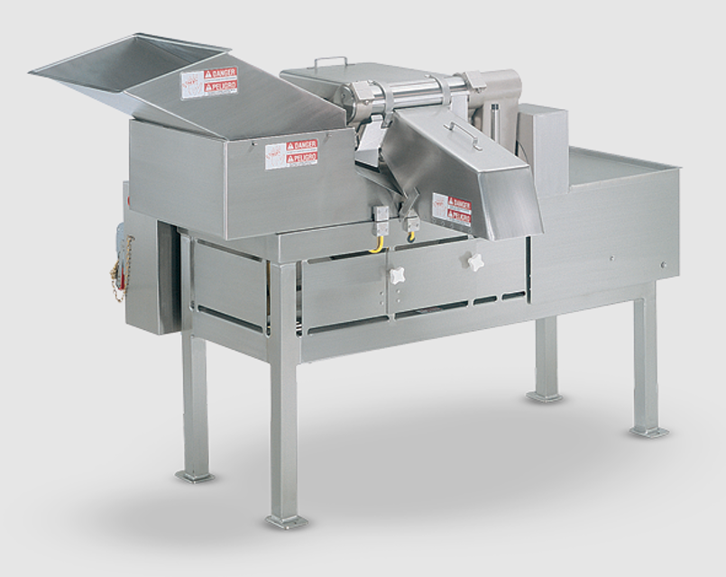
Urschel Laboratories Dicer Machine GK-A
Need answers fast?
Explore the manual using AI.
Turn manuals into instant answers
with your AI-powered assistantTurn manuals into instant answers
with your AI-powered assistant
Manual for Urschel Laboratories Dicer Machine GK-A
Complete asset maintenance, one click away
Get instant access to all the maintenance information you need. Empower technicians to perform preventive maintenance with asset packages, ready to use right out of the box.

Documents & Manuals
Find all the essential guides in one place.
 Tensioning Guide
- Belt-diagram
- C-120 pulleys
+ 13 more

Work Order Templates
Pre-built workflows to keep your asset running smoothly.
- Daily Electrical System Inspection
- Replace Roller and Pulley
- Install Engine B-120
+ 29 more

Procedures
Integrate maintenance plans directly into your work orders.
- Motion Industries
- Applied Industrial Technologies
- Electrical Brothers
+ 5 more

Parts
Access the parts list for your equipment in MaintainX.
- Drive Motor
- B2 Rollers
- Tensioning System
+ 40 more
Urschel Laboratories Dicer Machine GK-A
Create an account to install this asset package.
Maintenance Plans for Urschel Laboratories Dicer Machine Model GK-A
Integrate maintenance plans directly into your work orders in MaintainX.
Cover / Guard Removal
WARNING: Disconnect and lockout power source and visually verify that machine has come to a complete stop before removing any cover or guard. Do not operate this machine if any cover or guard is removed. Operating machine with covers or guards removed may result in serious injury!
Remove the following covers and guards to service the various areas of the machine (Figure 24, page 31):
Discharge chute: remove to service dicing unit.
Motor cover: release latch (Figure 22) and tilt away to service drive train and gears.
Feed hopper and hopper extension: remove to service slicing unit.
Chip chute enclosure: remove to service dicing unit.
Bottom grid: generally does not require removal.
Gear guard: remove to service drive train.
Drive guard: generally does not require removal.

Drive Train Disassembly
Warning: Disconnect and lock out power source before proceeding.
Remove all covers and guards and swing dicing unit into maintenance position.
Remove the impeller, slice case and drive belts.
Loosen the two set screws in gear hub on main drive shaft.
Use a hammer and a brass rod to drive shaft out of gear assembly.
Slide shaft back into position, meshing the small gear on drive shaft and the gear on jack shaft.
Remove drive pulley and key.
Remove cap screw from small gear on drive shaft, then slide gear and thrust washer off shaft.
Pull main drive shaft from main support casting.
Safety Switch Test
WARNING: There is a problem in the safety switch circuit if the LEDs are not lit as indicated or if, having removed a cover or guard equipped with switch, the machine can be started. DO NOT operate the machine in this condition! Call a qualified electrician to locate and repair the fault immediately. See “Inspection”, page 58.
With all covers and guards in place, turn the power disconnect switch to “I” (ON). Only the green “relay condition” LEDs on the amplifier should be lit. Turn power disconnect switch to “O” (OFF).
Remove or open one cover or guard equipped with switch. Turn power disconnect switch to “I” (ON). Only the red “relay condition” LEDs and the red “switch output” LEDs corresponding to the switch on the removed or open cover should be lit on the amplifier.
If LEDs are lit correctly, push the “I” (START) button. The safety switch circuit has been interrupted and machine should NOT start.
If the machine does start, that safety circuit has failed. Push the “O” (STOP) button, then disconnect and lock out power source.
Turn the power disconnect switch to “O” (OFF) and replace or close the cover or guard.
Individually remove or open each additional cover or guard equipped with switch and repeat steps 2 and 3. Make sure all covers and guards are securely in place after all switches have been tested.
Sign off on the safety switch test
Slicing Unit Disassembly
WARNING: Wear protective gloves when handling cutting parts. Cutting parts are sharp and can cause injury.
Power source disconnected and locked out?
Upload a photo of the disconnected power source
Discharge chute, chip chute enclosure, shield and feed hopper removed?
Upload a photo of the removed parts
Slicing knife holder removed?
Upload a photo of the removed slicing knife holder
Slicing knife removed from holder?
Upload a photo of the removed slicing knife
Bearing Block Replacement
Warning: This procedure requires trained personnel with specific tools!
If you lack the necessary tools or skills, return the crosscut knife spindles to Urschel Laboratories for repair.
Check off the tools you have available
Are all necessary tools available?
If not all tools are available, stop the procedure and return the spindle to Urschel Laboratories.
Was the procedure successful?
Describe any issues encountered during the procedure.
Sign off on the bearing block replacement
Parts for Urschel Laboratories Dicer Machine GK-A
Access the parts list for your equipment in MaintainX.
Brake Assembly, 10 Pound Foot With 110 Volt Coil, 56200, Use With Vfd Electrical Assembly, (Includes Items 3-20)
12897
Brake Assembly, 10 Pound Foot With 220 Volt Coil, 56200, Use With Across The Line Electrical Assemblies, (Includes Items 3-20)
12898
Brake Assembly, 10 Pound Foot With 575 Volt Coil, 56200, Use With Across The Line Electrical Assemblies, (Includes Items 3-20).
12899
K4 Solenoid Coil, 110-120 Volts
12884
K4 Solenoid Coil, 200-240 Volts
12885
Unlock efficiency
with MaintainX CoPilot
MaintainX CoPilot is your expert colleague, on call 24/7, helping your team find the answers they need to keep equipment running.
Reduce Unplanned Downtime
Ensure your team follows consistent procedures to minimize equipment failures and costly delays.
Maximize Asset Availability
Keep your assets running longer and more reliably, with standardized maintenance workflows from OEM manuals.
Lower Maintenance Costs
Turn any technician into an expert to streamline operations, maintain more assets, and reduce overall costs.
Thousands of companies manage their assets with MaintainX

'%3e%3cpath%20fill='url(%23b)'%20d='M66.008%2080.068c-5.084-.786-9.763-3.834-12.442-8.68a16.942%2016.942%200%200%201-1.87-5.18c1.096.19%202.203.476%203.298.87%206.525%202.333%2010.836%207.68%2011.014%2012.99ZM51.47%2061.576c.488-5.524%203.62-10.716%208.847-13.597a17.132%2017.132%200%200%201%2011.335-1.882c-.798%208.145-7.43%2014.848-16.038%2015.599-1.417.119-2.799.07-4.144-.12Zm28.564-11.478a17.513%2017.513%200%200%201%203.727%204.62c4.608%208.335%201.584%2018.813-6.75%2023.409a16.988%2016.988%200%200%201-4.359%201.679%2019.624%2019.624%200%200%201-3.977-12.776c.346-7.561%204.942-13.931%2011.36-16.932Z'/%3e%3cpath%20fill='%23110F0D'%20fill-rule='evenodd'%20d='M142.831%2048.324h4.977V77.03h-4.977V48.324Zm27.278%2013.002c.322%201.048.453%202.263.453%203.62v12.073h-4.787V66.208c0-.75-.047-1.572-.154-2.143-.453-2.382-1.822-3.572-4.215-3.572-2.31%200-3.882%201.274-4.43%203.476-.143.596-.226%201.405-.226%202.25v10.8h-4.787V56.623h4.477v2.989c1.536-2.5%203.906-3.43%206.371-3.43%203.488%200%206.263%201.68%207.298%205.144Zm24.636%207.323c0%203.882-2.358%206.525-5.763%207.727-1.298.453-2.632.643-4.62.643h-10.169V48.324h9.085c1.691%200%203.156.143%204.049.38%203.465.93%205.727%203.68%205.727%207.335%200%202.441-.81%204.156-2.762%205.644%202.905%201.417%204.453%203.727%204.453%206.966Zm-15.634-8.656h4.584c1.024%200%201.917-.143%202.536-.417%201.215-.548%201.905-1.608%201.905-3.167%200-1.548-.643-2.572-1.845-3.132-.691-.31-1.762-.452-2.763-.452h-4.417v7.168Zm10.716%208.465c0-1.536-.893-3.37-3.227-3.893-.428-.095-1.036-.143-1.571-.143h-5.918v8.085h5.501c.56%200%201.429-.048%201.953-.167%201.94-.453%203.262-1.846%203.262-3.882Zm47.747-11.847-8.097%2020.408h-4.429l-8.109-20.408h5.191l5.192%2014.574%205.108-14.574h5.144Zm-20.218%2010.002c0%20.69-.036%201.262-.155%201.94h-15.943c.631%202.87%202.714%204.728%205.882%204.728%202.131%200%203.607-.882%204.703-2.525h4.87c-1.762%204.144-5.204%206.692-9.657%206.692-6.084%200-10.537-4.858-10.537-10.49%200-6.108%204.524-10.776%2010.335-10.776%206.239%200%2010.442%204.954%2010.502%2010.43Zm-4.763-1.405c-.333-2.846-2.643-4.858-5.691-4.858-2.894%200-5.287%201.929-5.621%204.858h11.312Zm-72.667%203.44c0%204.787-3.287%208.371-9.419%208.371H119.363V64.66c-1.917.274-3.87.69-5.811%201.238l4.537%2011.121h-5.418l-3.596-9.585c-5.144%202.084-10.085%205.216-14.217%209.585h-4.786L101.8%2048.312h4.56l5.68%2013.883a44.112%2044.112%200%200%201%207.323-1.774V48.312h9.084c1.703%200%203.156.143%204.061.393%203.453.929%205.727%203.667%205.727%207.323%200%201.917-.738%204.179-2.81%205.691%203.06%201.56%204.501%204.025%204.501%206.93Zm-15.634-8.667a62.664%2062.664%200%200%201%202.06-.036c1.703.012%203.239.131%204.608.37%201.441-.549%202.357-1.727%202.357-3.537%200-1.941-.881-3.144-2.488-3.667-.548-.18-1.358-.286-2.322-.286h-4.215v7.156Zm-16.55%203.905-3.715-9.894-6.394%2016.502c2.833-2.595%206.263-4.858%2010.109-6.608Zm27.254%204.74c0-2.775-3.131-4.347-8.513-4.418-.715%200-1.441.011-2.191.047v8.252h5.918c2.548%200%204.786-1.37%204.786-3.882Z'%20clip-rule='evenodd'/%3e%3c/g%3e%3cdefs%3e%3clinearGradient%20id='b'%20x1='51.47'%20x2='85.916'%20y1='62.946'%20y2='62.946'%20gradientUnits='userSpaceOnUse'%3e%3cstop%20stop-color='%23CD9F28'/%3e%3cstop%20offset='1'%20stop-color='%23ECD80B'/%3e%3c/linearGradient%3e%3cclipPath%20id='a'%3e%3cpath%20fill='%23fff'%20d='M51.47%2045.728h186.104V80.14H51.47z'/%3e%3c/clipPath%3e%3c/defs%3e%3c/svg%3e)


Explore Other Assets


© 2026 MaintainX. All rights reserved.