


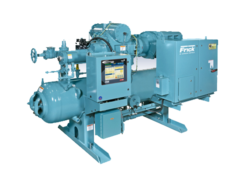
Frick Rotary Screw Compressor RWF II 496
Need answers fast?
Explore the manual using AI.
Turn manuals into instant answers
with your AI-powered assistantTurn manuals into instant answers
with your AI-powered assistant
Manual for Frick Rotary Screw Compressor RWF II 496
Complete asset maintenance, one click away
Get instant access to all the maintenance information you need. Empower technicians to perform preventive maintenance with asset packages, ready to use right out of the box.

Documents & Manuals
Find all the essential guides in one place.
 Tensioning Guide
- Belt-diagram
- C-120 pulleys
+ 13 more

Work Order Templates
Pre-built workflows to keep your asset running smoothly.
- Daily Electrical System Inspection
- Replace Roller and Pulley
- Install Engine B-120
+ 29 more

Procedures
Integrate maintenance plans directly into your work orders.
- Motion Industries
- Applied Industrial Technologies
- Electrical Brothers
+ 5 more

Parts
Access the parts list for your equipment in MaintainX.
- Drive Motor
- B2 Rollers
- Tensioning System
+ 40 more
Frick Rotary Screw Compressor RWF II 496
Create an account to install this asset package.
Maintenance Plans for Frick Rotary Screw Compressor Model RWF II 496
Integrate maintenance plans directly into your work orders in MaintainX.
5000 Hourly Strainers Cleaning
Clean oil strainers
Strainer - demand oil pump
To clean the demand oil pump strainer, the unit must be shut down. The procedure is as follows:
1. Push [STOP] key on microprocessor panel to shutdown unit, then open disconnect switches for compressor and oil pump motor starters.
2. Close strainer inlet service valve.
3. Open drain valve located in the strainer cover and drain oil into a container.
4. Remove capscrews securing strainer cover, strainer cover, gasket and element. Retain gasket.
5. Wash element in solvent and blow clean with air.
6. Wipe strainer body cavity clean with a lint-free clean cloth.

200 Hourly Strainers Cleaning
Clean oil strainers
Strainer - demand oil pump
To clean the demand oil pump strainer, the unit must be shut down. The procedure is as follows:
1. Push [STOP] key on microprocessor panel to shutdown unit, then open disconnect switches for compressor and oil pump motor starters.
2. Close strainer inlet service valve.
3. Open drain valve located in the strainer cover and drain oil into a container.
4. Remove capscrews securing strainer cover, strainer cover, gasket and element. Retain gasket.
5. Wash element in solvent and blow clean with air.
6. Wipe strainer body cavity clean with a lint-free clean cloth.
Oil Level Transmitter Replacement
The Oil Level Transmitter is located on the front of the separator near the bottom/center. See Figure 52.
The linear transmitter with hermetic enclosure is based on the capacitive measuring principle.
It features removable electronics (from the sensor well) eliminating the need to evacuate the compressor for replacement. This transmitter is dedicated to oil level control and has no user adjustments.
Shut off control power.
Remove DIN connector plug from transmitter.
Loosen set screws.
Remove transmitter unit.
Install new transmitter unit.
Tighten set screws.
6 Monthly Oil Analysis
Oil quality and analysis
WARNING: Do not mix oils of different brands, manufacturers, or types. Mixing of oils may cause excessive oil foaming, nuisance oil level cutouts, oil pressure loss, gas or oil leakage and catastrophic compressor failure.
NOTICE: The Frick oil charge shipped with the unit is the best suited lubricant for the conditions specified at the time of purchase. If there is any doubt due to the refrigerant, operating pressures, or temperatures, refer to Frick Oil publication 160.802-SPC for guidance. Only use Frick oil filter elements or warranty claim may be denied.
Participate in a regular, periodic oil analysis program to maintain oil and system integrity. Oil analysis kit part number: 333Q0001853.
Oil samples for analysis should be taken after the oil filter. A 1/4 in. purge valve is provided in the oil filter canister head.
Oil sampling procedure
WARNING: Exercise extreme caution in the vicinity of operating equipment. Skin contact with lube oil or inhalation of vapors can cause serious injury or death, consider gloves and eye protection.
Sample hot, active fluid while the equipment is operating. Sample after 30 min of compressor operation.
Unthread the oil sampling valve cap and locknut.
Rotary Screw Compressor Maintenance
Maintenance
General information
This section provides instructions for normal maintenance, a recommended maintenance program, troubleshooting and correction guides, and typical P and I diagrams. For typical wiring diagrams and information about the Quantum™ HD control panel, refer to 090.040-M.
WARNING
This section must be read and understood before attempting to perform any maintenance or service to the unit.
Normal maintenance operations
When performing maintenance you must take several precautions to ensure your safety:
WARNING
1. If unit is running, press [stop] key.
Parts for Frick Rotary Screw Compressor RWF II 496
Access the parts list for your equipment in MaintainX.
Rotary Screw Compressor
US2430129999900010
Frick Optical Isolation Kits
639C0133G01
Oil Analysis Kit
333Q0001853
Rotary Screw Compressor
US2430129999900010
Frick Optical Isolation Kits
639C0133G01
Oil Analysis Kit
333Q0001853
Rotary Screw Compressor
US2430129999900010
Frick Optical Isolation Kits
639C0133G01
Oil Analysis Kit
333Q0001853
Unlock efficiency
with MaintainX CoPilot
MaintainX CoPilot is your expert colleague, on call 24/7, helping your team find the answers they need to keep equipment running.
Reduce Unplanned Downtime
Ensure your team follows consistent procedures to minimize equipment failures and costly delays.
Maximize Asset Availability
Keep your assets running longer and more reliably, with standardized maintenance workflows from OEM manuals.
Lower Maintenance Costs
Turn any technician into an expert to streamline operations, maintain more assets, and reduce overall costs.
Thousands of companies manage their assets with MaintainX

'%3e%3cpath%20fill='url(%23b)'%20d='M66.008%2080.068c-5.084-.786-9.763-3.834-12.442-8.68a16.942%2016.942%200%200%201-1.87-5.18c1.096.19%202.203.476%203.298.87%206.525%202.333%2010.836%207.68%2011.014%2012.99ZM51.47%2061.576c.488-5.524%203.62-10.716%208.847-13.597a17.132%2017.132%200%200%201%2011.335-1.882c-.798%208.145-7.43%2014.848-16.038%2015.599-1.417.119-2.799.07-4.144-.12Zm28.564-11.478a17.513%2017.513%200%200%201%203.727%204.62c4.608%208.335%201.584%2018.813-6.75%2023.409a16.988%2016.988%200%200%201-4.359%201.679%2019.624%2019.624%200%200%201-3.977-12.776c.346-7.561%204.942-13.931%2011.36-16.932Z'/%3e%3cpath%20fill='%23110F0D'%20fill-rule='evenodd'%20d='M142.831%2048.324h4.977V77.03h-4.977V48.324Zm27.278%2013.002c.322%201.048.453%202.263.453%203.62v12.073h-4.787V66.208c0-.75-.047-1.572-.154-2.143-.453-2.382-1.822-3.572-4.215-3.572-2.31%200-3.882%201.274-4.43%203.476-.143.596-.226%201.405-.226%202.25v10.8h-4.787V56.623h4.477v2.989c1.536-2.5%203.906-3.43%206.371-3.43%203.488%200%206.263%201.68%207.298%205.144Zm24.636%207.323c0%203.882-2.358%206.525-5.763%207.727-1.298.453-2.632.643-4.62.643h-10.169V48.324h9.085c1.691%200%203.156.143%204.049.38%203.465.93%205.727%203.68%205.727%207.335%200%202.441-.81%204.156-2.762%205.644%202.905%201.417%204.453%203.727%204.453%206.966Zm-15.634-8.656h4.584c1.024%200%201.917-.143%202.536-.417%201.215-.548%201.905-1.608%201.905-3.167%200-1.548-.643-2.572-1.845-3.132-.691-.31-1.762-.452-2.763-.452h-4.417v7.168Zm10.716%208.465c0-1.536-.893-3.37-3.227-3.893-.428-.095-1.036-.143-1.571-.143h-5.918v8.085h5.501c.56%200%201.429-.048%201.953-.167%201.94-.453%203.262-1.846%203.262-3.882Zm47.747-11.847-8.097%2020.408h-4.429l-8.109-20.408h5.191l5.192%2014.574%205.108-14.574h5.144Zm-20.218%2010.002c0%20.69-.036%201.262-.155%201.94h-15.943c.631%202.87%202.714%204.728%205.882%204.728%202.131%200%203.607-.882%204.703-2.525h4.87c-1.762%204.144-5.204%206.692-9.657%206.692-6.084%200-10.537-4.858-10.537-10.49%200-6.108%204.524-10.776%2010.335-10.776%206.239%200%2010.442%204.954%2010.502%2010.43Zm-4.763-1.405c-.333-2.846-2.643-4.858-5.691-4.858-2.894%200-5.287%201.929-5.621%204.858h11.312Zm-72.667%203.44c0%204.787-3.287%208.371-9.419%208.371H119.363V64.66c-1.917.274-3.87.69-5.811%201.238l4.537%2011.121h-5.418l-3.596-9.585c-5.144%202.084-10.085%205.216-14.217%209.585h-4.786L101.8%2048.312h4.56l5.68%2013.883a44.112%2044.112%200%200%201%207.323-1.774V48.312h9.084c1.703%200%203.156.143%204.061.393%203.453.929%205.727%203.667%205.727%207.323%200%201.917-.738%204.179-2.81%205.691%203.06%201.56%204.501%204.025%204.501%206.93Zm-15.634-8.667a62.664%2062.664%200%200%201%202.06-.036c1.703.012%203.239.131%204.608.37%201.441-.549%202.357-1.727%202.357-3.537%200-1.941-.881-3.144-2.488-3.667-.548-.18-1.358-.286-2.322-.286h-4.215v7.156Zm-16.55%203.905-3.715-9.894-6.394%2016.502c2.833-2.595%206.263-4.858%2010.109-6.608Zm27.254%204.74c0-2.775-3.131-4.347-8.513-4.418-.715%200-1.441.011-2.191.047v8.252h5.918c2.548%200%204.786-1.37%204.786-3.882Z'%20clip-rule='evenodd'/%3e%3c/g%3e%3cdefs%3e%3clinearGradient%20id='b'%20x1='51.47'%20x2='85.916'%20y1='62.946'%20y2='62.946'%20gradientUnits='userSpaceOnUse'%3e%3cstop%20stop-color='%23CD9F28'/%3e%3cstop%20offset='1'%20stop-color='%23ECD80B'/%3e%3c/linearGradient%3e%3cclipPath%20id='a'%3e%3cpath%20fill='%23fff'%20d='M51.47%2045.728h186.104V80.14H51.47z'/%3e%3c/clipPath%3e%3c/defs%3e%3c/svg%3e)


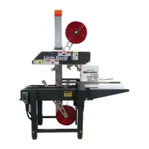
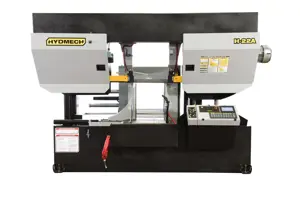
More from Frick


Explore Other Assets


© 2026 MaintainX. All rights reserved.