


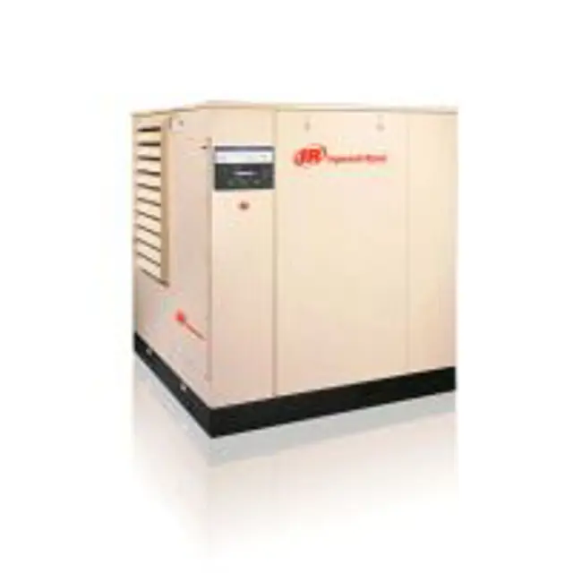
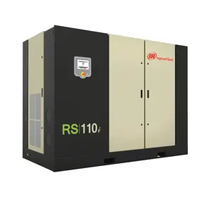
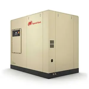
Ingersoll Rand Compressor SSR-MH37
Need answers fast?
Explore the manual using AI.
Turn manuals into instant answers
with your AI-powered assistantTurn manuals into instant answers
with your AI-powered assistant
Manual for Ingersoll Rand Compressor SSR-MH37
Complete asset maintenance, one click away
Get instant access to all the maintenance information you need. Empower technicians to perform preventive maintenance with asset packages, ready to use right out of the box.

Documents & Manuals
Find all the essential guides in one place.
 Tensioning Guide
- Belt-diagram
- C-120 pulleys
+ 13 more

Work Order Templates
Pre-built workflows to keep your asset running smoothly.
- Daily Electrical System Inspection
- Replace Roller and Pulley
- Install Engine B-120
+ 29 more

Procedures
Integrate maintenance plans directly into your work orders.
- Motion Industries
- Applied Industrial Technologies
- Electrical Brothers
+ 5 more

Parts
Access the parts list for your equipment in MaintainX.
- Drive Motor
- B2 Rollers
- Tensioning System
+ 40 more
Ingersoll Rand Compressor SSR-MH37
Create an account to install this asset package.
Maintenance Plans for Ingersoll Rand Compressor Model SSR-MH37
Integrate maintenance plans directly into your work orders in MaintainX.
9 Monthly / 2000 Hourly Motor Lubrication
Warning: This procedure requires trained personnel with PPE!
All 60 Hz ODP drive motors and all fan motors.
Grease relief along shaft can occur, precluding necessity of removing this plug if inaccessible.
The inlet grease gun fittings and outlet plugs (or spring-loaded reliefs) are located at each end of the motor housing.
The drive end reliefs protrude out the circumference of the lower portion of the end bell near a flange bolt.
The drive end outlet plugs are located just behind the flange in the air intake area at about the 5 or 6 o’clock position.
Free drain hole of any hard grease (use piece of wire if necessary).
Use a hand lever type grease gun.
Determine in advance the quantity of grease delivered with each stroke of the lever.

1 Yearly / 4000 Hourly Separator Cleaning
Tools Required: Open end wrench, Pliers
The screen/orifice assemblies are similar in appearance to a straight tubing connector and will be located between two pieces of 1/4 inch O.D. scavenge line tubing.
The main body is made from 1/2 inch hexagon shaped steel and the diameter of the orifice and a direction-of-flow arrow is stamped in flat areas of the hexagon.
A removable screen and orifice is located in the exit end of the assembly and will require cleaning.
To remove the screen/orifice, disconnect the scavenge line tubing from each end. Hold the center section firmly and use a pair of pliers to gently grasp the exit end of the assembly that seals against the scavenge line tubing.
Pull the end out of the center section while using care to prevent damage to the screen or sealing surfaces.
Clean and inspect all parts prior to reinstallation.
When the assembly is installed, confirm the direction of flow to be correct. Observe the small arrow stamped in the center section and ensure the direction flow to be from the separator tank to the airend.
Sign off on the separator cleaning
6 Monthly / 4000 Hourly Air Compressor Maintenance
Clean - Cooler cores
Clean cooler cores if discharge air temperature is excessive or if unit shutdown occurs on high air temperature.
Ensure that the compressor is isolated from the compressed air system by closing the isolation valve and venting pressure from the drip leg.
Ensure that the main power disconnect switch is locked open and tagged.
Tools Required
■ Screwdriver
■ Wrench set
■ Air hose equipped with approved O.S.H.A. nozzle.
On units sold outside the U.S.A. consult local codes.
6 Monthly / 2000 Hourly Coolant Filter Replacement
Replace - Coolant filter.
In very clean operating environments and where inlet filter is changed at the above prescribed intervals.
In extremely dirty environments change coolant, filters, and separator elements more frequently.
The coolant filter should be changed after the first 150 hours of operation and every 2000 hours thereafter, or when the coolant is being changed. In dirty operating environments the filter should be changed more frequently.
Use a suitable device and loosen the old element. Use drain pan to catch any leakage during removal. Discard old element.
Wipe the sealing surface of the filter with a clean, lint-free rag to prevent the entry of dirt into the system.
Remove the replacement element from its protective package. Apply a small amount of clean lubricant on the rubber seal and install the element.
Screw element/s on until the seal makes contact with the head of the filter assembly. Tighten approximately one-half turn additional.
Start unit and check for leaks.
Coolant Separator Element Check
Run compressor in full load mode and at rated pressure
Enter the display message from the 'SEPARATOR PRESSURE DROP'
If warning light is on and display says 'CHG SEPR ELEMENT', proceed with the following steps
Loosen the fitting that holds the scavenge tube into the tank and withdraw the tube assembly
Disconnect blowdown valve from elbow in tank cover
Disconnect tube from fitting on minimum pressure check valve
Loosen tube nut on same tube at aftercooler inlet then swing tube away from tank cover
Remove the bolts that hold the tank cover in position and remove cover
Lift the separator element up and out of the tank and discard the faulty element
Unlock efficiency
with MaintainX CoPilot
MaintainX CoPilot is your expert colleague, on call 24/7, helping your team find the answers they need to keep equipment running.
Reduce Unplanned Downtime
Ensure your team follows consistent procedures to minimize equipment failures and costly delays.
Maximize Asset Availability
Keep your assets running longer and more reliably, with standardized maintenance workflows from OEM manuals.
Lower Maintenance Costs
Turn any technician into an expert to streamline operations, maintain more assets, and reduce overall costs.
Thousands of companies manage their assets with MaintainX

'%3e%3cpath%20fill='url(%23b)'%20d='M66.008%2080.068c-5.084-.786-9.763-3.834-12.442-8.68a16.942%2016.942%200%200%201-1.87-5.18c1.096.19%202.203.476%203.298.87%206.525%202.333%2010.836%207.68%2011.014%2012.99ZM51.47%2061.576c.488-5.524%203.62-10.716%208.847-13.597a17.132%2017.132%200%200%201%2011.335-1.882c-.798%208.145-7.43%2014.848-16.038%2015.599-1.417.119-2.799.07-4.144-.12Zm28.564-11.478a17.513%2017.513%200%200%201%203.727%204.62c4.608%208.335%201.584%2018.813-6.75%2023.409a16.988%2016.988%200%200%201-4.359%201.679%2019.624%2019.624%200%200%201-3.977-12.776c.346-7.561%204.942-13.931%2011.36-16.932Z'/%3e%3cpath%20fill='%23110F0D'%20fill-rule='evenodd'%20d='M142.831%2048.324h4.977V77.03h-4.977V48.324Zm27.278%2013.002c.322%201.048.453%202.263.453%203.62v12.073h-4.787V66.208c0-.75-.047-1.572-.154-2.143-.453-2.382-1.822-3.572-4.215-3.572-2.31%200-3.882%201.274-4.43%203.476-.143.596-.226%201.405-.226%202.25v10.8h-4.787V56.623h4.477v2.989c1.536-2.5%203.906-3.43%206.371-3.43%203.488%200%206.263%201.68%207.298%205.144Zm24.636%207.323c0%203.882-2.358%206.525-5.763%207.727-1.298.453-2.632.643-4.62.643h-10.169V48.324h9.085c1.691%200%203.156.143%204.049.38%203.465.93%205.727%203.68%205.727%207.335%200%202.441-.81%204.156-2.762%205.644%202.905%201.417%204.453%203.727%204.453%206.966Zm-15.634-8.656h4.584c1.024%200%201.917-.143%202.536-.417%201.215-.548%201.905-1.608%201.905-3.167%200-1.548-.643-2.572-1.845-3.132-.691-.31-1.762-.452-2.763-.452h-4.417v7.168Zm10.716%208.465c0-1.536-.893-3.37-3.227-3.893-.428-.095-1.036-.143-1.571-.143h-5.918v8.085h5.501c.56%200%201.429-.048%201.953-.167%201.94-.453%203.262-1.846%203.262-3.882Zm47.747-11.847-8.097%2020.408h-4.429l-8.109-20.408h5.191l5.192%2014.574%205.108-14.574h5.144Zm-20.218%2010.002c0%20.69-.036%201.262-.155%201.94h-15.943c.631%202.87%202.714%204.728%205.882%204.728%202.131%200%203.607-.882%204.703-2.525h4.87c-1.762%204.144-5.204%206.692-9.657%206.692-6.084%200-10.537-4.858-10.537-10.49%200-6.108%204.524-10.776%2010.335-10.776%206.239%200%2010.442%204.954%2010.502%2010.43Zm-4.763-1.405c-.333-2.846-2.643-4.858-5.691-4.858-2.894%200-5.287%201.929-5.621%204.858h11.312Zm-72.667%203.44c0%204.787-3.287%208.371-9.419%208.371H119.363V64.66c-1.917.274-3.87.69-5.811%201.238l4.537%2011.121h-5.418l-3.596-9.585c-5.144%202.084-10.085%205.216-14.217%209.585h-4.786L101.8%2048.312h4.56l5.68%2013.883a44.112%2044.112%200%200%201%207.323-1.774V48.312h9.084c1.703%200%203.156.143%204.061.393%203.453.929%205.727%203.667%205.727%207.323%200%201.917-.738%204.179-2.81%205.691%203.06%201.56%204.501%204.025%204.501%206.93Zm-15.634-8.667a62.664%2062.664%200%200%201%202.06-.036c1.703.012%203.239.131%204.608.37%201.441-.549%202.357-1.727%202.357-3.537%200-1.941-.881-3.144-2.488-3.667-.548-.18-1.358-.286-2.322-.286h-4.215v7.156Zm-16.55%203.905-3.715-9.894-6.394%2016.502c2.833-2.595%206.263-4.858%2010.109-6.608Zm27.254%204.74c0-2.775-3.131-4.347-8.513-4.418-.715%200-1.441.011-2.191.047v8.252h5.918c2.548%200%204.786-1.37%204.786-3.882Z'%20clip-rule='evenodd'/%3e%3c/g%3e%3cdefs%3e%3clinearGradient%20id='b'%20x1='51.47'%20x2='85.916'%20y1='62.946'%20y2='62.946'%20gradientUnits='userSpaceOnUse'%3e%3cstop%20stop-color='%23CD9F28'/%3e%3cstop%20offset='1'%20stop-color='%23ECD80B'/%3e%3c/linearGradient%3e%3cclipPath%20id='a'%3e%3cpath%20fill='%23fff'%20d='M51.47%2045.728h186.104V80.14H51.47z'/%3e%3c/clipPath%3e%3c/defs%3e%3c/svg%3e)


More from Ingersoll Rand


Explore Other Assets


© 2026 MaintainX. All rights reserved.