


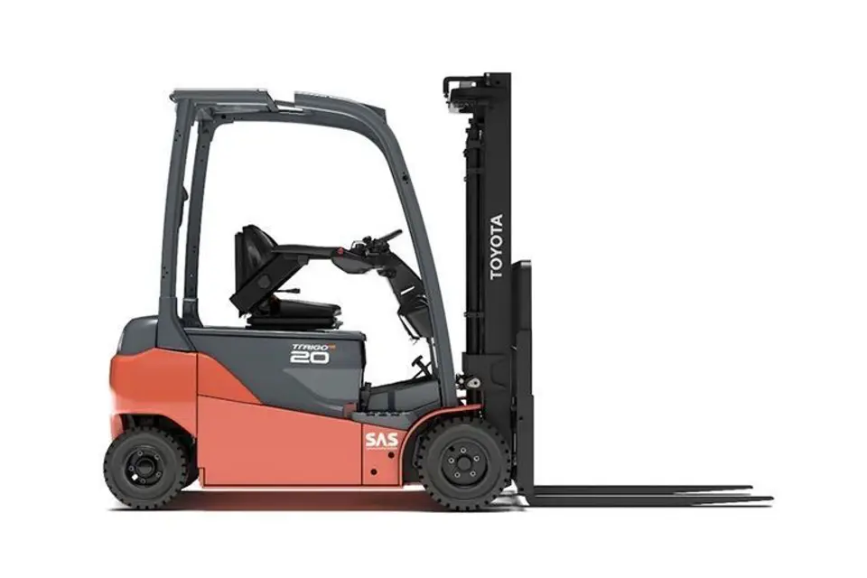
Toyota Forklift 8FBMK20T
Need answers fast?
Explore the manual using AI.
Turn manuals into instant answers
with your AI-powered assistantTurn manuals into instant answers
with your AI-powered assistant
Manual for Toyota Forklift 8FBMK20T
Complete asset maintenance, one click away
Get instant access to all the maintenance information you need. Empower technicians to perform preventive maintenance with asset packages, ready to use right out of the box.

Documents & Manuals
Find all the essential guides in one place.
 Tensioning Guide
- Belt-diagram
- C-120 pulleys
+ 13 more

Work Order Templates
Pre-built workflows to keep your asset running smoothly.
- Daily Electrical System Inspection
- Replace Roller and Pulley
- Install Engine B-120
+ 29 more

Procedures
Integrate maintenance plans directly into your work orders.
- Motion Industries
- Applied Industrial Technologies
- Electrical Brothers
+ 5 more

Parts
Access the parts list for your equipment in MaintainX.
- Drive Motor
- B2 Rollers
- Tensioning System
+ 40 more
Toyota Forklift 8FBMK20T
Create an account to install this asset package.
Maintenance Plans for Toyota Forklift Model 8FBMK20T
Integrate maintenance plans directly into your work orders in MaintainX.
Lift Cylinder Rod Adjusting Rings Adjustment
NOTICE! For double lift cylinders, check and adjust in order to prevent the irregular lifting on the right and left sides caused by loads beyond the permitted limits, etc.
NOTICE! Check and adjust where required when replacing any of the following elements: Lift cylinder ASSY, lift cylinder rod SUB-ASSY, lift cylinder SUB-ASSY, mast ASSY, outer mast SUB-ASSY and inner mast SUB-ASSY
NOTICE! Having completed the adjustments, align the SAS system.
1. Inspection method.
Slowly lift the inner mast and check that the right and left cylinder rod stop when the inner mast reaches maximum height.
- Normal conditions:
The right and left rods stop more or less simultaneously with almost no vibrations on the inner mast.
- Abnormal condition:
The rods stop at a slightly different time and the upper part of the inner mast vibrates as they stop. To correct the defect, add adjustment rings to the cylinder which stops first.

Hydraulic Steering System Pressure Inspection
Install an oil pressure gauge
Disconnect the hose from the steering valve port and connect the adapter (SST). SST 09450-23610-71
Install the oil pressure gauge. Plug size: PT1/8
Start the motor and turn the steering wheel
Start the motor and turn the steering wheel slowly clockwise and then anti-clockwise.
Measure the pressure at the time of discharge.
Check the standard value
Is the measured pressure between 9.1 to 9.6 MPa?
Adjustment if standard value is not obtained
Tilting Cylinders Disassembling
Remove the footboard
Remove the tilt cover
Set the mast in vertical position and disconnect the hose
Remove the tilting cylinder front pin
Remove the tilting cylinder rear pin
Remove the tilting cylinder
NOTICE! If both tilting cylinders are removed fix the mast with a chain in order to avoid the mast overturning
Reassembly Procedure: The assembly procedure is the reverse of the disassembly procedure
NOTICE! Before installation, apply grease to the front and rear pin seats on the tilting cylinder (Shell Mobil Grease special or equivalent)
Fork Carriage Disassembling
1) Remove the guide shoes.
2) Slacken the adjustment screw.
3) Remove the snap ring. [Point 1]
4) Remove the roller. [Point 1]
Reassembly Procedure:
The assembly procedure is the reverse of the disassembly procedure.;
Rear Axle Hub Joint Disassembling
Raise the rear of the vehicle
Remove the rear wheels
Remove the hub cap
Remove the castellated nut and self-locking washer
Remove the hub with the outer bearing
Remove the hub
Remove the inner ball bearing and oil gasket
Disconnect the tension rod (on the cast articulated joint side)
Remove the steering pin
Unlock efficiency
with MaintainX CoPilot
MaintainX CoPilot is your expert colleague, on call 24/7, helping your team find the answers they need to keep equipment running.
Reduce Unplanned Downtime
Ensure your team follows consistent procedures to minimize equipment failures and costly delays.
Maximize Asset Availability
Keep your assets running longer and more reliably, with standardized maintenance workflows from OEM manuals.
Lower Maintenance Costs
Turn any technician into an expert to streamline operations, maintain more assets, and reduce overall costs.
Thousands of companies manage their assets with MaintainX

'%3e%3cpath%20fill='url(%23b)'%20d='M66.008%2080.068c-5.084-.786-9.763-3.834-12.442-8.68a16.942%2016.942%200%200%201-1.87-5.18c1.096.19%202.203.476%203.298.87%206.525%202.333%2010.836%207.68%2011.014%2012.99ZM51.47%2061.576c.488-5.524%203.62-10.716%208.847-13.597a17.132%2017.132%200%200%201%2011.335-1.882c-.798%208.145-7.43%2014.848-16.038%2015.599-1.417.119-2.799.07-4.144-.12Zm28.564-11.478a17.513%2017.513%200%200%201%203.727%204.62c4.608%208.335%201.584%2018.813-6.75%2023.409a16.988%2016.988%200%200%201-4.359%201.679%2019.624%2019.624%200%200%201-3.977-12.776c.346-7.561%204.942-13.931%2011.36-16.932Z'/%3e%3cpath%20fill='%23110F0D'%20fill-rule='evenodd'%20d='M142.831%2048.324h4.977V77.03h-4.977V48.324Zm27.278%2013.002c.322%201.048.453%202.263.453%203.62v12.073h-4.787V66.208c0-.75-.047-1.572-.154-2.143-.453-2.382-1.822-3.572-4.215-3.572-2.31%200-3.882%201.274-4.43%203.476-.143.596-.226%201.405-.226%202.25v10.8h-4.787V56.623h4.477v2.989c1.536-2.5%203.906-3.43%206.371-3.43%203.488%200%206.263%201.68%207.298%205.144Zm24.636%207.323c0%203.882-2.358%206.525-5.763%207.727-1.298.453-2.632.643-4.62.643h-10.169V48.324h9.085c1.691%200%203.156.143%204.049.38%203.465.93%205.727%203.68%205.727%207.335%200%202.441-.81%204.156-2.762%205.644%202.905%201.417%204.453%203.727%204.453%206.966Zm-15.634-8.656h4.584c1.024%200%201.917-.143%202.536-.417%201.215-.548%201.905-1.608%201.905-3.167%200-1.548-.643-2.572-1.845-3.132-.691-.31-1.762-.452-2.763-.452h-4.417v7.168Zm10.716%208.465c0-1.536-.893-3.37-3.227-3.893-.428-.095-1.036-.143-1.571-.143h-5.918v8.085h5.501c.56%200%201.429-.048%201.953-.167%201.94-.453%203.262-1.846%203.262-3.882Zm47.747-11.847-8.097%2020.408h-4.429l-8.109-20.408h5.191l5.192%2014.574%205.108-14.574h5.144Zm-20.218%2010.002c0%20.69-.036%201.262-.155%201.94h-15.943c.631%202.87%202.714%204.728%205.882%204.728%202.131%200%203.607-.882%204.703-2.525h4.87c-1.762%204.144-5.204%206.692-9.657%206.692-6.084%200-10.537-4.858-10.537-10.49%200-6.108%204.524-10.776%2010.335-10.776%206.239%200%2010.442%204.954%2010.502%2010.43Zm-4.763-1.405c-.333-2.846-2.643-4.858-5.691-4.858-2.894%200-5.287%201.929-5.621%204.858h11.312Zm-72.667%203.44c0%204.787-3.287%208.371-9.419%208.371H119.363V64.66c-1.917.274-3.87.69-5.811%201.238l4.537%2011.121h-5.418l-3.596-9.585c-5.144%202.084-10.085%205.216-14.217%209.585h-4.786L101.8%2048.312h4.56l5.68%2013.883a44.112%2044.112%200%200%201%207.323-1.774V48.312h9.084c1.703%200%203.156.143%204.061.393%203.453.929%205.727%203.667%205.727%207.323%200%201.917-.738%204.179-2.81%205.691%203.06%201.56%204.501%204.025%204.501%206.93Zm-15.634-8.667a62.664%2062.664%200%200%201%202.06-.036c1.703.012%203.239.131%204.608.37%201.441-.549%202.357-1.727%202.357-3.537%200-1.941-.881-3.144-2.488-3.667-.548-.18-1.358-.286-2.322-.286h-4.215v7.156Zm-16.55%203.905-3.715-9.894-6.394%2016.502c2.833-2.595%206.263-4.858%2010.109-6.608Zm27.254%204.74c0-2.775-3.131-4.347-8.513-4.418-.715%200-1.441.011-2.191.047v8.252h5.918c2.548%200%204.786-1.37%204.786-3.882Z'%20clip-rule='evenodd'/%3e%3c/g%3e%3cdefs%3e%3clinearGradient%20id='b'%20x1='51.47'%20x2='85.916'%20y1='62.946'%20y2='62.946'%20gradientUnits='userSpaceOnUse'%3e%3cstop%20stop-color='%23CD9F28'/%3e%3cstop%20offset='1'%20stop-color='%23ECD80B'/%3e%3c/linearGradient%3e%3cclipPath%20id='a'%3e%3cpath%20fill='%23fff'%20d='M51.47%2045.728h186.104V80.14H51.47z'/%3e%3c/clipPath%3e%3c/defs%3e%3c/svg%3e)


More from Toyota
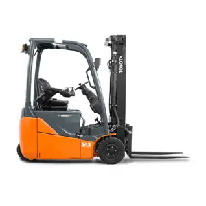
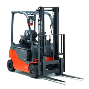
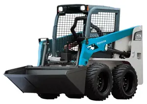


Explore Other Assets


© 2026 MaintainX. All rights reserved.