


JCB Loader 437
Need answers fast?
Explore the manual using AI.
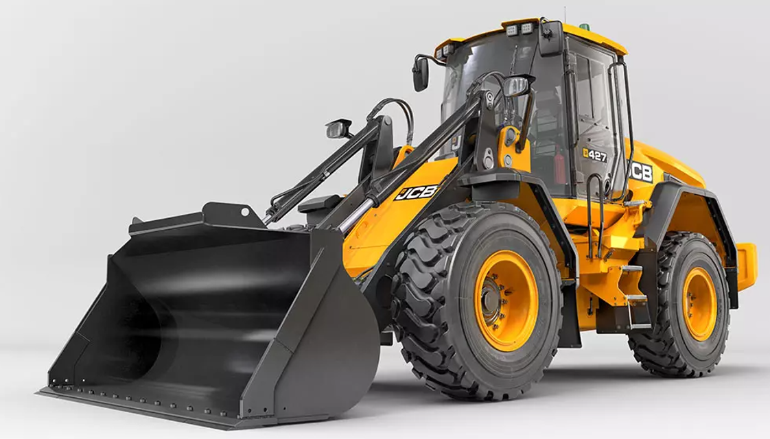
The JCB Loader 437 is a versatile and powerful piece of industrial equipment designed for heavy-duty applications. Known for its robust performance and reliability, this loader excels in construction and agricultural tasks, making it an essential asset for any operation. With advanced features and efficient operation, the JCB Loader 437 stands out in its class.
Turn manuals into instant answers
with your AI-powered assistantTurn manuals into instant answers
with your AI-powered assistant
Manual for JCB Loader 437
Complete asset maintenance, one click away
Get instant access to all the maintenance information you need. Empower technicians to perform preventive maintenance with asset packages, ready to use right out of the box.

Documents & Manuals
Find all the essential guides in one place.
 Tensioning Guide
- Belt-diagram
- C-120 pulleys
+ 13 more

Work Order Templates
Pre-built workflows to keep your asset running smoothly.
- Daily Electrical System Inspection
- Replace Roller and Pulley
- Install Engine B-120
+ 29 more

Procedures
Integrate maintenance plans directly into your work orders.
- Motion Industries
- Applied Industrial Technologies
- Electrical Brothers
+ 5 more

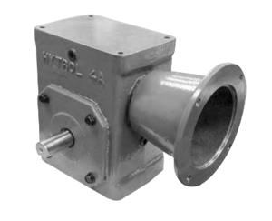
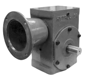
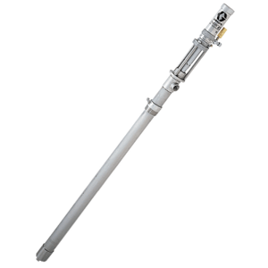
Parts
Access the parts list for your equipment in MaintainX.
- Drive Motor
- B2 Rollers
- Tensioning System
+ 40 more
JCB Loader 437
Create an account to install this asset package.
Maintenance Plans for JCB Loader Model 437
Integrate maintenance plans directly into your work orders in MaintainX.
Lift Arm Installation
If you must raise the lift arm to get access to perform a non-routine maintenance procedure, a lift arm support devices must be used.
Lift arm support devices are supplied with a machine as an option and your machine may not be equippedwith them. Do not attempt to carry out maintenance operations beneath a raised lift arm unless you use the correct lift arm support devices.
Install the Maintenance Struts (If supplied)
1. If necessary, empty the shovel.
2. Make sure that the machine is parked correctly in the straight-ahead position on solid, level ground.
3. Make sure that the park brake is engaged and the transmission is in neutral.
4. Raise the lift arm sufficiently to install the maintenance struts.
5. Run the engine at idle for a few minutes to let the turbocharger cool. Duration: 2–3min
6. Stop the engine.

Hydraulic Pressure Installation
The installation procedure is the opposite of the removal procedure. Additionally do the following steps
1. Use a press to install the new bush and then replace the seal.
2. Install the spacer shims as necessary.;
Attachment Engage
1. Align the machine square with the attachment.
2. Lower the lift arm until the pivot shaft is below the level of the hooks on the attachment. Refer to Figure 17.
3. Drive the machine slowly forward, stop when the pivot shaft just touches the attachment.
4. Engage the park brake and put the transmission in neutral.
5. Raise the lift arms and engage the pivot shaft into the hooks. Stop the movement as soon as the pivot shaft is engaged.
6. Engage the attachment:
6.1. Proportional lever control: Move the lever to the left and tilt the Quickhitch fully back.
6.2. Refer to loader control decal in the cab for exact location of button as differ2ent loader control levers are available.
6.3. Multi lever control option: Move the lever to the rear and tilt the Quickhitch fully back.
Attachment Disengage
Park the machine on solid, level ground
Engage the park brake and put the transmission in neutral
If necessary, disconnect the hydraulic hoses
Push and hold the Quickhitch isolator switch
Disengage the locking pins:Refer to Figure 13
Proportional lever control with an auxiliary button: Push the auxiliary 1 button until the locking pins are retracted
Refer to loader control decal in the cab for exact location of button as different loader control levers are available
Multi lever control option: Push the lever until the locking pins are retracted
Release the Quickhitch isolator switch
Hydraulic Pressure Removal
Make the machine safe with the lift arm lowered. Refer to (PIL 01-03).
Install the articulation strut. Refer to (PIL 06-27).
Isolate the battery from the electrical circuit. Refer to (PIL 33-03).
Use suitable lifting equipment to support the quickhitch.
Disconnect the hydraulic hoses.
Remove the bolts and the pivot pins from both sides of the quickhitch.
Remove the quickhitch from the lift arms.
Check the condition of the bushes and seals.
Replace the bushes and seals if they are damaged or worn.
Unlock efficiency
with MaintainX CoPilot
MaintainX CoPilot is your expert colleague, on call 24/7, helping your team find the answers they need to keep equipment running.
Reduce Unplanned Downtime
Ensure your team follows consistent procedures to minimize equipment failures and costly delays.
Maximize Asset Availability
Keep your assets running longer and more reliably, with standardized maintenance workflows from OEM manuals.
Lower Maintenance Costs
Turn any technician into an expert to streamline operations, maintain more assets, and reduce overall costs.
Thousands of companies manage their assets with MaintainX

'%3e%3cpath%20fill='url(%23b)'%20d='M66.008%2080.068c-5.084-.786-9.763-3.834-12.442-8.68a16.942%2016.942%200%200%201-1.87-5.18c1.096.19%202.203.476%203.298.87%206.525%202.333%2010.836%207.68%2011.014%2012.99ZM51.47%2061.576c.488-5.524%203.62-10.716%208.847-13.597a17.132%2017.132%200%200%201%2011.335-1.882c-.798%208.145-7.43%2014.848-16.038%2015.599-1.417.119-2.799.07-4.144-.12Zm28.564-11.478a17.513%2017.513%200%200%201%203.727%204.62c4.608%208.335%201.584%2018.813-6.75%2023.409a16.988%2016.988%200%200%201-4.359%201.679%2019.624%2019.624%200%200%201-3.977-12.776c.346-7.561%204.942-13.931%2011.36-16.932Z'/%3e%3cpath%20fill='%23110F0D'%20fill-rule='evenodd'%20d='M142.831%2048.324h4.977V77.03h-4.977V48.324Zm27.278%2013.002c.322%201.048.453%202.263.453%203.62v12.073h-4.787V66.208c0-.75-.047-1.572-.154-2.143-.453-2.382-1.822-3.572-4.215-3.572-2.31%200-3.882%201.274-4.43%203.476-.143.596-.226%201.405-.226%202.25v10.8h-4.787V56.623h4.477v2.989c1.536-2.5%203.906-3.43%206.371-3.43%203.488%200%206.263%201.68%207.298%205.144Zm24.636%207.323c0%203.882-2.358%206.525-5.763%207.727-1.298.453-2.632.643-4.62.643h-10.169V48.324h9.085c1.691%200%203.156.143%204.049.38%203.465.93%205.727%203.68%205.727%207.335%200%202.441-.81%204.156-2.762%205.644%202.905%201.417%204.453%203.727%204.453%206.966Zm-15.634-8.656h4.584c1.024%200%201.917-.143%202.536-.417%201.215-.548%201.905-1.608%201.905-3.167%200-1.548-.643-2.572-1.845-3.132-.691-.31-1.762-.452-2.763-.452h-4.417v7.168Zm10.716%208.465c0-1.536-.893-3.37-3.227-3.893-.428-.095-1.036-.143-1.571-.143h-5.918v8.085h5.501c.56%200%201.429-.048%201.953-.167%201.94-.453%203.262-1.846%203.262-3.882Zm47.747-11.847-8.097%2020.408h-4.429l-8.109-20.408h5.191l5.192%2014.574%205.108-14.574h5.144Zm-20.218%2010.002c0%20.69-.036%201.262-.155%201.94h-15.943c.631%202.87%202.714%204.728%205.882%204.728%202.131%200%203.607-.882%204.703-2.525h4.87c-1.762%204.144-5.204%206.692-9.657%206.692-6.084%200-10.537-4.858-10.537-10.49%200-6.108%204.524-10.776%2010.335-10.776%206.239%200%2010.442%204.954%2010.502%2010.43Zm-4.763-1.405c-.333-2.846-2.643-4.858-5.691-4.858-2.894%200-5.287%201.929-5.621%204.858h11.312Zm-72.667%203.44c0%204.787-3.287%208.371-9.419%208.371H119.363V64.66c-1.917.274-3.87.69-5.811%201.238l4.537%2011.121h-5.418l-3.596-9.585c-5.144%202.084-10.085%205.216-14.217%209.585h-4.786L101.8%2048.312h4.56l5.68%2013.883a44.112%2044.112%200%200%201%207.323-1.774V48.312h9.084c1.703%200%203.156.143%204.061.393%203.453.929%205.727%203.667%205.727%207.323%200%201.917-.738%204.179-2.81%205.691%203.06%201.56%204.501%204.025%204.501%206.93Zm-15.634-8.667a62.664%2062.664%200%200%201%202.06-.036c1.703.012%203.239.131%204.608.37%201.441-.549%202.357-1.727%202.357-3.537%200-1.941-.881-3.144-2.488-3.667-.548-.18-1.358-.286-2.322-.286h-4.215v7.156Zm-16.55%203.905-3.715-9.894-6.394%2016.502c2.833-2.595%206.263-4.858%2010.109-6.608Zm27.254%204.74c0-2.775-3.131-4.347-8.513-4.418-.715%200-1.441.011-2.191.047v8.252h5.918c2.548%200%204.786-1.37%204.786-3.882Z'%20clip-rule='evenodd'/%3e%3c/g%3e%3cdefs%3e%3clinearGradient%20id='b'%20x1='51.47'%20x2='85.916'%20y1='62.946'%20y2='62.946'%20gradientUnits='userSpaceOnUse'%3e%3cstop%20stop-color='%23CD9F28'/%3e%3cstop%20offset='1'%20stop-color='%23ECD80B'/%3e%3c/linearGradient%3e%3cclipPath%20id='a'%3e%3cpath%20fill='%23fff'%20d='M51.47%2045.728h186.104V80.14H51.47z'/%3e%3c/clipPath%3e%3c/defs%3e%3c/svg%3e)


More from JCB


Explore Other Assets


© 2026 MaintainX. All rights reserved.