


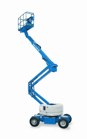
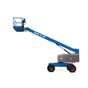
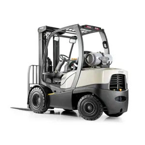
Genie Articulated Boom Lift S85/2WD
Need answers fast?
Explore the manual using AI.

The Genie Articulated Boom Lift S85/2WD is a versatile aerial work platform designed for enhanced reach and maneuverability in various industrial applications. Known for its robust performance and reliability, this model is ideal for construction, maintenance, and other demanding tasks requiring elevated access.
Turn manuals into instant answers
with your AI-powered assistantTurn manuals into instant answers
with your AI-powered assistant
Manual for Genie Articulated Boom Lift S85/2WD
Complete asset maintenance, one click away
Get instant access to all the maintenance information you need. Empower technicians to perform preventive maintenance with asset packages, ready to use right out of the box.

Documents & Manuals
Find all the essential guides in one place.
 Tensioning Guide
- Belt-diagram
- C-120 pulleys
+ 13 more

Work Order Templates
Pre-built workflows to keep your asset running smoothly.
- Daily Electrical System Inspection
- Replace Roller and Pulley
- Install Engine B-120
+ 29 more

Procedures
Integrate maintenance plans directly into your work orders.
- Motion Industries
- Applied Industrial Technologies
- Electrical Brothers
+ 5 more

Parts
Access the parts list for your equipment in MaintainX.
- Drive Motor
- B2 Rollers
- Tensioning System
+ 40 more
Genie Articulated Boom Lift S85/2WD
Create an account to install this asset package.
Maintenance Plans for Genie Articulated Boom Lift Model S85/2WD
Integrate maintenance plans directly into your work orders in MaintainX.
1 Yearly Boom Extend/Retract Cables Inspection
- Inspect the Boom Extend/Retract Cables
Manufacturers specifications require that this procedure be performed by personnel that are competent in cable / wire rope inspection
Note: Additional or more frequent inspections may be required due to the following:
• exposed to hostile or corrosive environmental conditions
• boom is overloaded
• sustains a shock load
• electrical arcing
• unused for extended periods
The boom extend/retract cables are responsible for the extension and retraction of the boom tubes

2000 Hourly Hydraulic Oil Maintenance
- Test or Replace the Hydraulic Oil
Replacement or testing of the hydraulic oil is essential for good machine performance and service life. Dirty oil and a clogged suction strainer or hydraulic filters may cause the machine to perform poorly and continued use may cause component damage. Extremely dirty conditions may require oil changes to be performed more frequently
Note: Before replacing the hydraulic oil, the oil may be tested by an oil distributor for specific levels of contamination to verify that changing the oil is necessary. If the hydraulic oil is not replaced at the 2000 hour inspection, test the oil quarterly. Replace the oil when it fails the test
Note: When removing a hose assembly or fitting, the O-ring (if equipped) on the fitting and/or hose end must be replaced. All connections must be torqued to specification during installation. Refer to Specifications, Hydraulic Hose and Fitting Torque Specifications
Testing the oil:
Complete the hydraulic oil testing with an oil distributor
If the hydraulic oil passes testing at the 2000 hour maintenance interval, the oil must be tested every quarter by an oil distributor until the oil fails the test and is replaced
If the hydraulic oil fails testing at the 2000 hour maintenance interval, the oil must be replaced
After the oil has been replaced, continue the scheduled quarterly maintenance inspection
100 Hourly GM .998L Engine Maintanance
Check Coolant level
Check Oil level
Check for leaks Oil, fuel and coolant systems
Replace engine oil and filter
Drain/clean LPG vaporizer
Check PCV valve
Clean/replace air cleaner element
Check timing belt
Check electrical wiring for chafing or damage
3 Monthly Boom Extend/Retract Cables Maintenance
Warning: This procedure must be performed by personnel competent in cable/wire rope inspection.
Note: Additional or more frequent inspections may be required due to hostile or corrosive environmental conditions, boom overload, shock load, electrical arcing, or extended periods of disuse.
Inspect and adjust the boom extend/retract cables. Are they in good condition?
Inspect for foreign objects, damage and/or improper adjustment of the boom extend/retract cables and related components. Any issues found?
Check the boom extend and retract functions. Do they operate smoothly and free of hesitation, jerking and unusual noise?
Refer to the appropriate procedure for your model
Sign off on the boom extend/retract cables maintenance
3 Monthly Safety Envelope And Circuits Maintenance
- Test the Safety Envelope and Circuits - S-100, S-105, S-120, S-125, S-100HD and S-120HD
Testing the machine safety envelope is critical to safe machine operation. If the boom is allowed to operate when a safety switch is not functioning correctly, the machine stability is compromised and may tip over
Note: Use the following chart to identify the description of each LCD screen control button used in this procedure
1. Start the engine from the ground controls
2. Raise the boom to approximately 60°
S-100, S-105 and S-100HD Models: Proceed to step 28
101 feet / 30.8 m Length Safety Switch, LSB2RS:
3. Extend the boom to more than 80 feet / 24.4 m
4. Push in the red Emergency Stop button to the off position
Parts for Genie Articulated Boom Lift S85/2WD
Access the parts list for your equipment in MaintainX.
O-ring Field Service Kit
49612
Digital Level Kit
58351
Digital Protractor
58377
O-ring Field Service Kit
49612
Digital Level Kit
58351
Digital Protractor
58377
O-ring Field Service Kit
49612
Digital Level Kit
58351
Digital Protractor
58377
Unlock efficiency
with MaintainX CoPilot
MaintainX CoPilot is your expert colleague, on call 24/7, helping your team find the answers they need to keep equipment running.
Reduce Unplanned Downtime
Ensure your team follows consistent procedures to minimize equipment failures and costly delays.
Maximize Asset Availability
Keep your assets running longer and more reliably, with standardized maintenance workflows from OEM manuals.
Lower Maintenance Costs
Turn any technician into an expert to streamline operations, maintain more assets, and reduce overall costs.
Thousands of companies manage their assets with MaintainX

'%3e%3cpath%20fill='url(%23b)'%20d='M66.008%2080.068c-5.084-.786-9.763-3.834-12.442-8.68a16.942%2016.942%200%200%201-1.87-5.18c1.096.19%202.203.476%203.298.87%206.525%202.333%2010.836%207.68%2011.014%2012.99ZM51.47%2061.576c.488-5.524%203.62-10.716%208.847-13.597a17.132%2017.132%200%200%201%2011.335-1.882c-.798%208.145-7.43%2014.848-16.038%2015.599-1.417.119-2.799.07-4.144-.12Zm28.564-11.478a17.513%2017.513%200%200%201%203.727%204.62c4.608%208.335%201.584%2018.813-6.75%2023.409a16.988%2016.988%200%200%201-4.359%201.679%2019.624%2019.624%200%200%201-3.977-12.776c.346-7.561%204.942-13.931%2011.36-16.932Z'/%3e%3cpath%20fill='%23110F0D'%20fill-rule='evenodd'%20d='M142.831%2048.324h4.977V77.03h-4.977V48.324Zm27.278%2013.002c.322%201.048.453%202.263.453%203.62v12.073h-4.787V66.208c0-.75-.047-1.572-.154-2.143-.453-2.382-1.822-3.572-4.215-3.572-2.31%200-3.882%201.274-4.43%203.476-.143.596-.226%201.405-.226%202.25v10.8h-4.787V56.623h4.477v2.989c1.536-2.5%203.906-3.43%206.371-3.43%203.488%200%206.263%201.68%207.298%205.144Zm24.636%207.323c0%203.882-2.358%206.525-5.763%207.727-1.298.453-2.632.643-4.62.643h-10.169V48.324h9.085c1.691%200%203.156.143%204.049.38%203.465.93%205.727%203.68%205.727%207.335%200%202.441-.81%204.156-2.762%205.644%202.905%201.417%204.453%203.727%204.453%206.966Zm-15.634-8.656h4.584c1.024%200%201.917-.143%202.536-.417%201.215-.548%201.905-1.608%201.905-3.167%200-1.548-.643-2.572-1.845-3.132-.691-.31-1.762-.452-2.763-.452h-4.417v7.168Zm10.716%208.465c0-1.536-.893-3.37-3.227-3.893-.428-.095-1.036-.143-1.571-.143h-5.918v8.085h5.501c.56%200%201.429-.048%201.953-.167%201.94-.453%203.262-1.846%203.262-3.882Zm47.747-11.847-8.097%2020.408h-4.429l-8.109-20.408h5.191l5.192%2014.574%205.108-14.574h5.144Zm-20.218%2010.002c0%20.69-.036%201.262-.155%201.94h-15.943c.631%202.87%202.714%204.728%205.882%204.728%202.131%200%203.607-.882%204.703-2.525h4.87c-1.762%204.144-5.204%206.692-9.657%206.692-6.084%200-10.537-4.858-10.537-10.49%200-6.108%204.524-10.776%2010.335-10.776%206.239%200%2010.442%204.954%2010.502%2010.43Zm-4.763-1.405c-.333-2.846-2.643-4.858-5.691-4.858-2.894%200-5.287%201.929-5.621%204.858h11.312Zm-72.667%203.44c0%204.787-3.287%208.371-9.419%208.371H119.363V64.66c-1.917.274-3.87.69-5.811%201.238l4.537%2011.121h-5.418l-3.596-9.585c-5.144%202.084-10.085%205.216-14.217%209.585h-4.786L101.8%2048.312h4.56l5.68%2013.883a44.112%2044.112%200%200%201%207.323-1.774V48.312h9.084c1.703%200%203.156.143%204.061.393%203.453.929%205.727%203.667%205.727%207.323%200%201.917-.738%204.179-2.81%205.691%203.06%201.56%204.501%204.025%204.501%206.93Zm-15.634-8.667a62.664%2062.664%200%200%201%202.06-.036c1.703.012%203.239.131%204.608.37%201.441-.549%202.357-1.727%202.357-3.537%200-1.941-.881-3.144-2.488-3.667-.548-.18-1.358-.286-2.322-.286h-4.215v7.156Zm-16.55%203.905-3.715-9.894-6.394%2016.502c2.833-2.595%206.263-4.858%2010.109-6.608Zm27.254%204.74c0-2.775-3.131-4.347-8.513-4.418-.715%200-1.441.011-2.191.047v8.252h5.918c2.548%200%204.786-1.37%204.786-3.882Z'%20clip-rule='evenodd'/%3e%3c/g%3e%3cdefs%3e%3clinearGradient%20id='b'%20x1='51.47'%20x2='85.916'%20y1='62.946'%20y2='62.946'%20gradientUnits='userSpaceOnUse'%3e%3cstop%20stop-color='%23CD9F28'/%3e%3cstop%20offset='1'%20stop-color='%23ECD80B'/%3e%3c/linearGradient%3e%3cclipPath%20id='a'%3e%3cpath%20fill='%23fff'%20d='M51.47%2045.728h186.104V80.14H51.47z'/%3e%3c/clipPath%3e%3c/defs%3e%3c/svg%3e)


More from Genie


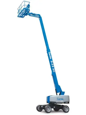

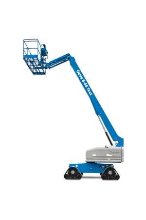
Explore Other Assets


© 2026 MaintainX. All rights reserved.