


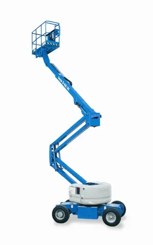
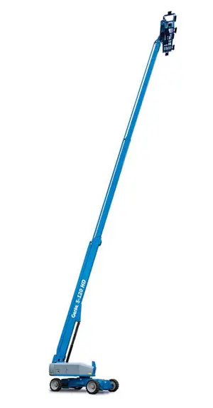
Genie Articulated Boom Lift S-80/4WD
Need answers fast?
Explore the manual using AI.

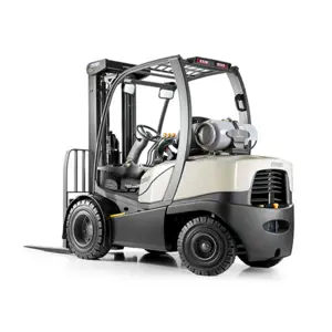
The Genie Articulated Boom Lift S-80/4WD is a versatile and robust aerial work platform designed for outdoor applications. With its advanced hydraulic system and exceptional reach, this boom lift ensures safety and efficiency for various construction and maintenance tasks. Ideal for professionals seeking reliable performance in challenging environments.
Turn manuals into instant answers
with your AI-powered assistantTurn manuals into instant answers
with your AI-powered assistant
Manual for Genie Articulated Boom Lift S-80/4WD
Complete asset maintenance, one click away
Get instant access to all the maintenance information you need. Empower technicians to perform preventive maintenance with asset packages, ready to use right out of the box.

Documents & Manuals
Find all the essential guides in one place.
 Tensioning Guide
- Belt-diagram
- C-120 pulleys
+ 13 more

Work Order Templates
Pre-built workflows to keep your asset running smoothly.
- Daily Electrical System Inspection
- Replace Roller and Pulley
- Install Engine B-120
+ 29 more

Procedures
Integrate maintenance plans directly into your work orders.
- Motion Industries
- Applied Industrial Technologies
- Electrical Brothers
+ 5 more

Parts
Access the parts list for your equipment in MaintainX.
- Drive Motor
- B2 Rollers
- Tensioning System
+ 40 more
Genie Articulated Boom Lift S-80/4WD
Create an account to install this asset package.
Maintenance Plans for Genie Articulated Boom Lift Model S-80/4WD
Integrate maintenance plans directly into your work orders in MaintainX.
3 Monthly Safety Envelope And Circuit Test
- Test the Safety Envelope and Circuits - Z-80/60
Testing the machine safety envelope is critical to safe machine operation. If the boom is allowed to operate when a safety switch is not functioning correctly, the machine stability is compromised and may tip over
For limit switch and angle sensor information, Refer to appropriate Service and Repair Manual for your machine
Note: Use the following chart to identify the description of each LCD screen control button used in this procedure
Secondary Boom #1 Angle Safety Limit Switch, LSS2AS
1. Turn the key switch to ground control and pull out the red Emergency Stop button to the on position at both ground and platform controls
2. Start the engine from the ground controls
3. Press the (plus)(minus) buttons on the LCD screen to activate status mode
4. Press the enter or previous button on the LCD screen until secondary boom length is displayed

50 Hourly Continental Engine Maintanance
- Visual Inspection of engine
- Check Oil level
- Check Air cleaner
- Check PCV system
- Check Coolant level
- Check for leaks Oil, fuel and coolant systems
- Clean Air filter discharge valve
- Replace Engine oil
- Replace Oil filter
1 Yearly Turntable Bearing Inspection
- Inspect for Turntable Bearing Wear
Periodic inspection of turntable bearing wear is essential to safe machine operation, good machine performance and service life. Continued use of a worn turntable bearing could create an unsafe operating condition, resulting in death or serious injury and component damage
Note: Perform this procedure with the machine on a firm, level surface with the boom in the stowed position
1. Grease the turntable bearing. Refer to Maintenance Procedure, Grease the Turntable Bearing and Rotate Gear
2. Torque the turntable bearing bolts to specification. Refer to Maintenance Procedure, Check the Turntable Rotation Bearing Bolts
3. S/SX-Booms: Using the ground controls, raise the boom to full height. Do not extend the boom
Z-Booms: Using the ground controls, raise the primary and secondary booms to full height. Do not extend the primary boom
Z-80/60, Z-135/70 and ZX-135/70: Using the ground controls, fully raise, but do not extend, the primary boom and jib. The secondary riser should remain in its stowed position
4. Place a dial indicator between the drive chassis and the turntable at a point that is directly under, or inline with, the boom and no more than 1 inch / 2.5 cm from the bearing
1 Daily Kubota Engine Maintanance
- Check Fuel hoses and clamp bands
- Replace Engine oil , Z482
- Check Fan belt tension and damage
- Check Battery electrolyte level
- Check Spark plug
- Clean Air cleaner element (Replace the element after 6 times cleaning)
- Clean Fuel filter (element type)
- Replace Oil filter cartridge, Z482
- Replace Oil filter cartridge, D1105, WG972
3 Monthly Exhaust System Check
- Check the Exhaust System
WARNING!
Bodily injury hazard. Do not inspect while the engine is running. Remove the key to secure from operation
CAUTION!
Burn hazard. Beware of hot engine components. Contact with hot engine components may result in severe burns
1. Be sure that all nuts and bolts are tight
2. Inspect all welds for cracks
3. Inspect for exhaust leaks; i.e., carbon buildup around seams and joints;
Parts for Genie Articulated Boom Lift S-80/4WD
Access the parts list for your equipment in MaintainX.
Digital Protractor
58377
O-ring Field Service Kit
49612
Digital Level Kit
58351
Digital Protractor
58377
O-ring Field Service Kit
49612
Digital Level Kit
58351
Digital Protractor
58377
O-ring Field Service Kit
49612
Digital Level Kit
58351
Unlock efficiency
with MaintainX CoPilot
MaintainX CoPilot is your expert colleague, on call 24/7, helping your team find the answers they need to keep equipment running.
Reduce Unplanned Downtime
Ensure your team follows consistent procedures to minimize equipment failures and costly delays.
Maximize Asset Availability
Keep your assets running longer and more reliably, with standardized maintenance workflows from OEM manuals.
Lower Maintenance Costs
Turn any technician into an expert to streamline operations, maintain more assets, and reduce overall costs.
Thousands of companies manage their assets with MaintainX

'%3e%3cpath%20fill='url(%23b)'%20d='M66.008%2080.068c-5.084-.786-9.763-3.834-12.442-8.68a16.942%2016.942%200%200%201-1.87-5.18c1.096.19%202.203.476%203.298.87%206.525%202.333%2010.836%207.68%2011.014%2012.99ZM51.47%2061.576c.488-5.524%203.62-10.716%208.847-13.597a17.132%2017.132%200%200%201%2011.335-1.882c-.798%208.145-7.43%2014.848-16.038%2015.599-1.417.119-2.799.07-4.144-.12Zm28.564-11.478a17.513%2017.513%200%200%201%203.727%204.62c4.608%208.335%201.584%2018.813-6.75%2023.409a16.988%2016.988%200%200%201-4.359%201.679%2019.624%2019.624%200%200%201-3.977-12.776c.346-7.561%204.942-13.931%2011.36-16.932Z'/%3e%3cpath%20fill='%23110F0D'%20fill-rule='evenodd'%20d='M142.831%2048.324h4.977V77.03h-4.977V48.324Zm27.278%2013.002c.322%201.048.453%202.263.453%203.62v12.073h-4.787V66.208c0-.75-.047-1.572-.154-2.143-.453-2.382-1.822-3.572-4.215-3.572-2.31%200-3.882%201.274-4.43%203.476-.143.596-.226%201.405-.226%202.25v10.8h-4.787V56.623h4.477v2.989c1.536-2.5%203.906-3.43%206.371-3.43%203.488%200%206.263%201.68%207.298%205.144Zm24.636%207.323c0%203.882-2.358%206.525-5.763%207.727-1.298.453-2.632.643-4.62.643h-10.169V48.324h9.085c1.691%200%203.156.143%204.049.38%203.465.93%205.727%203.68%205.727%207.335%200%202.441-.81%204.156-2.762%205.644%202.905%201.417%204.453%203.727%204.453%206.966Zm-15.634-8.656h4.584c1.024%200%201.917-.143%202.536-.417%201.215-.548%201.905-1.608%201.905-3.167%200-1.548-.643-2.572-1.845-3.132-.691-.31-1.762-.452-2.763-.452h-4.417v7.168Zm10.716%208.465c0-1.536-.893-3.37-3.227-3.893-.428-.095-1.036-.143-1.571-.143h-5.918v8.085h5.501c.56%200%201.429-.048%201.953-.167%201.94-.453%203.262-1.846%203.262-3.882Zm47.747-11.847-8.097%2020.408h-4.429l-8.109-20.408h5.191l5.192%2014.574%205.108-14.574h5.144Zm-20.218%2010.002c0%20.69-.036%201.262-.155%201.94h-15.943c.631%202.87%202.714%204.728%205.882%204.728%202.131%200%203.607-.882%204.703-2.525h4.87c-1.762%204.144-5.204%206.692-9.657%206.692-6.084%200-10.537-4.858-10.537-10.49%200-6.108%204.524-10.776%2010.335-10.776%206.239%200%2010.442%204.954%2010.502%2010.43Zm-4.763-1.405c-.333-2.846-2.643-4.858-5.691-4.858-2.894%200-5.287%201.929-5.621%204.858h11.312Zm-72.667%203.44c0%204.787-3.287%208.371-9.419%208.371H119.363V64.66c-1.917.274-3.87.69-5.811%201.238l4.537%2011.121h-5.418l-3.596-9.585c-5.144%202.084-10.085%205.216-14.217%209.585h-4.786L101.8%2048.312h4.56l5.68%2013.883a44.112%2044.112%200%200%201%207.323-1.774V48.312h9.084c1.703%200%203.156.143%204.061.393%203.453.929%205.727%203.667%205.727%207.323%200%201.917-.738%204.179-2.81%205.691%203.06%201.56%204.501%204.025%204.501%206.93Zm-15.634-8.667a62.664%2062.664%200%200%201%202.06-.036c1.703.012%203.239.131%204.608.37%201.441-.549%202.357-1.727%202.357-3.537%200-1.941-.881-3.144-2.488-3.667-.548-.18-1.358-.286-2.322-.286h-4.215v7.156Zm-16.55%203.905-3.715-9.894-6.394%2016.502c2.833-2.595%206.263-4.858%2010.109-6.608Zm27.254%204.74c0-2.775-3.131-4.347-8.513-4.418-.715%200-1.441.011-2.191.047v8.252h5.918c2.548%200%204.786-1.37%204.786-3.882Z'%20clip-rule='evenodd'/%3e%3c/g%3e%3cdefs%3e%3clinearGradient%20id='b'%20x1='51.47'%20x2='85.916'%20y1='62.946'%20y2='62.946'%20gradientUnits='userSpaceOnUse'%3e%3cstop%20stop-color='%23CD9F28'/%3e%3cstop%20offset='1'%20stop-color='%23ECD80B'/%3e%3c/linearGradient%3e%3cclipPath%20id='a'%3e%3cpath%20fill='%23fff'%20d='M51.47%2045.728h186.104V80.14H51.47z'/%3e%3c/clipPath%3e%3c/defs%3e%3c/svg%3e)


More from Genie


Explore Other Assets


© 2026 MaintainX. All rights reserved.