


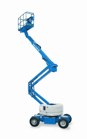
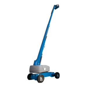
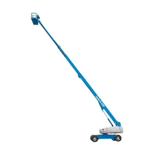
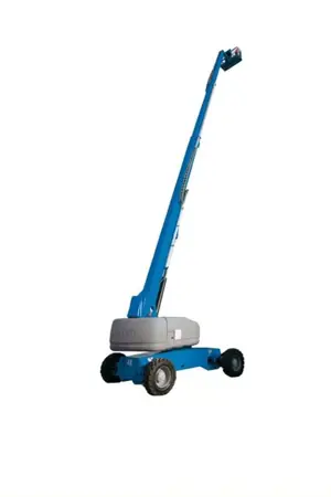
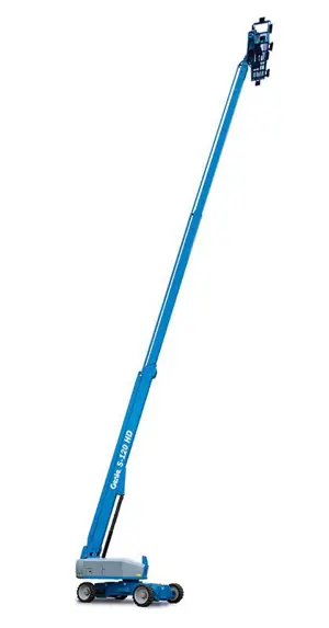
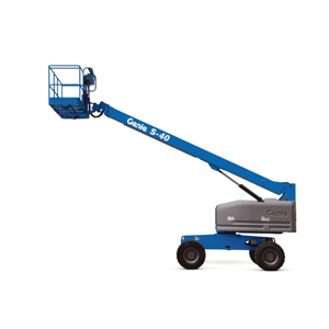
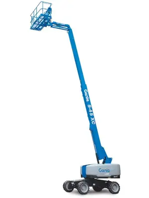
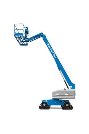
Genie Articulated Boom Lift Z-60/37 FE
Need answers fast?
Explore the manual using AI.

The Genie Articulated Boom Lift Z-60/37 FE is a versatile and reliable aerial work platform designed for various industrial applications. Known for its exceptional reach and maneuverability, this boom lift enhances productivity and safety on job sites, making it a preferred choice for contractors and maintenance professionals.
Turn manuals into instant answers
with your AI-powered assistantTurn manuals into instant answers
with your AI-powered assistant
Manual for Genie Articulated Boom Lift Z-60/37 FE
Complete asset maintenance, one click away
Get instant access to all the maintenance information you need. Empower technicians to perform preventive maintenance with asset packages, ready to use right out of the box.

Documents & Manuals
Find all the essential guides in one place.
 Tensioning Guide
- Belt-diagram
- C-120 pulleys
+ 13 more

Work Order Templates
Pre-built workflows to keep your asset running smoothly.
- Daily Electrical System Inspection
- Replace Roller and Pulley
- Install Engine B-120
+ 29 more

Procedures
Integrate maintenance plans directly into your work orders.
- Motion Industries
- Applied Industrial Technologies
- Electrical Brothers
+ 5 more

Parts
Access the parts list for your equipment in MaintainX.
- Drive Motor
- B2 Rollers
- Tensioning System
+ 40 more
Genie Articulated Boom Lift Z-60/37 FE
Create an account to install this asset package.
Maintenance Plans for Genie Articulated Boom Lift Model Z-60/37 FE
Integrate maintenance plans directly into your work orders in MaintainX.
Initial 50 Hours Boom Lift Maintenance
- Inspect the Tires, Wheels and Lug Nut Torque
- Grease the Turntable Rotation Bearing and Rotate Gear
- Check the Turntable Rotation Bearing Bolts
- Replace the Drive Hub Oil
- Replace the Hydraulic Filters;

3 Monthly Platform Self-Leveling Test
- Test the Platform Self-leveling
1. At the ground controls, lower the boom to the stowed position
2. Activate function enable and adjust the platform to a level position
3. Raise and lower the primary boom through a full cycle
Result: The platform should remain level at all times to within +/-5 degrees;
1 Yearly Key Switch Test
- Test the Key Switches - ALC1000 Models
Proper key switch action and response is essential to safe machine operation. Failure of either key switch to function properly could cause a hazardous operating situation
This maintenance procedure applies to the following models: S-100, S-100HD, S-105, S-120, S-120HD, S-125, SX-105 XC, SX-125 XC, SX-135 XC, SX-150, SX-180, Z-80/60, Z-135/70 and Zx-135/70
There are two key switches on the machine - the Main key switch and the Bypass/Recovery key switch
The Main key switch controls machine operation from the ground or platform controls
When the Bypass/Recovery key switch is turned to the bypass position, the primary boom can be elevated with the axles retracted (if equipped with retractable axles). This feature of the machine is especially helpful for storage purposes or when loading the machine for transport
When the Bypass/Recovery key switch is turned and held to the recovery position, the emergency power unit turns on and starts a sequence to lower the platform
This feature of the machine is especially helpful if the operator in the platform cannot lower the boom, if the platform controls become inoperative or for returning the machine to a safe position when the safety switches have been tripped
Note: Perform this procedure on a firm, level surface with the machine in the stowed position
3 Monthly Drive Speed Test
- Test the Drive Speed - Stowed Position
Note: Perform this procedure with the machine on a firm, level surface that is free of obstructions
Note: Perform this procedure with the machine in the stowed position
1. Create start and finish lines by marking two lines on the ground 40 feet / 12.2 m apart
2. Choose a point on the machine (i.e., contact patch of a tire) as a visual reference for use when crossing the start and finish lines
3. Bring the machine to top drive speed before reaching the start line. Begin timing when your reference point on the machine crosses the start line
4. Continue at full speed and note the time when the machine reference point crosses the finish line. Refer to Specifications, Drive Speed Specifications
- Test the Drive Speed - Raised or Extended Position
1. Create start and finish lines by marking two lines on the ground 40 feet / 12.2 m apart
3 Monthly Emergency Power System Test
- Test the Emergency Power System (excludes ALC-600 and ALC-1000 Models)
1. Turn the key switch to ground control and pull out the red Emergency Stop button to the on position at both the ground and platform controls
2. At the ground controls, break the security tie and lift the emergency power switch cover (if equipped)
3. Simultaneously hold the emergency power switch on and operate each boom function through a partial cycle
• Result: All boom functions operate
4. Close the emergency power switch cover and secure the cover with a security tie (if equipped)
5 Turn the key switch to platform controls
6. At the platform controls, break the security tie and lift the emergency power switch cover (if equipped). 7. Press down on the foot switch and simultaneously hold the emergency power switch on and operate each boom function through a partial cycle
• Result: All boom functions operate
Parts for Genie Articulated Boom Lift Z-60/37 FE
Access the parts list for your equipment in MaintainX.
O-ring Field Service Kit
49612
Digital Protractor
58377
Digital Level Kit
58351
O-ring Field Service Kit
49612
Digital Protractor
58377
Digital Level Kit
58351
O-ring Field Service Kit
49612
Digital Protractor
58377
Digital Level Kit
58351
Unlock efficiency
with MaintainX CoPilot
MaintainX CoPilot is your expert colleague, on call 24/7, helping your team find the answers they need to keep equipment running.
Reduce Unplanned Downtime
Ensure your team follows consistent procedures to minimize equipment failures and costly delays.
Maximize Asset Availability
Keep your assets running longer and more reliably, with standardized maintenance workflows from OEM manuals.
Lower Maintenance Costs
Turn any technician into an expert to streamline operations, maintain more assets, and reduce overall costs.
Thousands of companies manage their assets with MaintainX

'%3e%3cpath%20fill='url(%23b)'%20d='M66.008%2080.068c-5.084-.786-9.763-3.834-12.442-8.68a16.942%2016.942%200%200%201-1.87-5.18c1.096.19%202.203.476%203.298.87%206.525%202.333%2010.836%207.68%2011.014%2012.99ZM51.47%2061.576c.488-5.524%203.62-10.716%208.847-13.597a17.132%2017.132%200%200%201%2011.335-1.882c-.798%208.145-7.43%2014.848-16.038%2015.599-1.417.119-2.799.07-4.144-.12Zm28.564-11.478a17.513%2017.513%200%200%201%203.727%204.62c4.608%208.335%201.584%2018.813-6.75%2023.409a16.988%2016.988%200%200%201-4.359%201.679%2019.624%2019.624%200%200%201-3.977-12.776c.346-7.561%204.942-13.931%2011.36-16.932Z'/%3e%3cpath%20fill='%23110F0D'%20fill-rule='evenodd'%20d='M142.831%2048.324h4.977V77.03h-4.977V48.324Zm27.278%2013.002c.322%201.048.453%202.263.453%203.62v12.073h-4.787V66.208c0-.75-.047-1.572-.154-2.143-.453-2.382-1.822-3.572-4.215-3.572-2.31%200-3.882%201.274-4.43%203.476-.143.596-.226%201.405-.226%202.25v10.8h-4.787V56.623h4.477v2.989c1.536-2.5%203.906-3.43%206.371-3.43%203.488%200%206.263%201.68%207.298%205.144Zm24.636%207.323c0%203.882-2.358%206.525-5.763%207.727-1.298.453-2.632.643-4.62.643h-10.169V48.324h9.085c1.691%200%203.156.143%204.049.38%203.465.93%205.727%203.68%205.727%207.335%200%202.441-.81%204.156-2.762%205.644%202.905%201.417%204.453%203.727%204.453%206.966Zm-15.634-8.656h4.584c1.024%200%201.917-.143%202.536-.417%201.215-.548%201.905-1.608%201.905-3.167%200-1.548-.643-2.572-1.845-3.132-.691-.31-1.762-.452-2.763-.452h-4.417v7.168Zm10.716%208.465c0-1.536-.893-3.37-3.227-3.893-.428-.095-1.036-.143-1.571-.143h-5.918v8.085h5.501c.56%200%201.429-.048%201.953-.167%201.94-.453%203.262-1.846%203.262-3.882Zm47.747-11.847-8.097%2020.408h-4.429l-8.109-20.408h5.191l5.192%2014.574%205.108-14.574h5.144Zm-20.218%2010.002c0%20.69-.036%201.262-.155%201.94h-15.943c.631%202.87%202.714%204.728%205.882%204.728%202.131%200%203.607-.882%204.703-2.525h4.87c-1.762%204.144-5.204%206.692-9.657%206.692-6.084%200-10.537-4.858-10.537-10.49%200-6.108%204.524-10.776%2010.335-10.776%206.239%200%2010.442%204.954%2010.502%2010.43Zm-4.763-1.405c-.333-2.846-2.643-4.858-5.691-4.858-2.894%200-5.287%201.929-5.621%204.858h11.312Zm-72.667%203.44c0%204.787-3.287%208.371-9.419%208.371H119.363V64.66c-1.917.274-3.87.69-5.811%201.238l4.537%2011.121h-5.418l-3.596-9.585c-5.144%202.084-10.085%205.216-14.217%209.585h-4.786L101.8%2048.312h4.56l5.68%2013.883a44.112%2044.112%200%200%201%207.323-1.774V48.312h9.084c1.703%200%203.156.143%204.061.393%203.453.929%205.727%203.667%205.727%207.323%200%201.917-.738%204.179-2.81%205.691%203.06%201.56%204.501%204.025%204.501%206.93Zm-15.634-8.667a62.664%2062.664%200%200%201%202.06-.036c1.703.012%203.239.131%204.608.37%201.441-.549%202.357-1.727%202.357-3.537%200-1.941-.881-3.144-2.488-3.667-.548-.18-1.358-.286-2.322-.286h-4.215v7.156Zm-16.55%203.905-3.715-9.894-6.394%2016.502c2.833-2.595%206.263-4.858%2010.109-6.608Zm27.254%204.74c0-2.775-3.131-4.347-8.513-4.418-.715%200-1.441.011-2.191.047v8.252h5.918c2.548%200%204.786-1.37%204.786-3.882Z'%20clip-rule='evenodd'/%3e%3c/g%3e%3cdefs%3e%3clinearGradient%20id='b'%20x1='51.47'%20x2='85.916'%20y1='62.946'%20y2='62.946'%20gradientUnits='userSpaceOnUse'%3e%3cstop%20stop-color='%23CD9F28'/%3e%3cstop%20offset='1'%20stop-color='%23ECD80B'/%3e%3c/linearGradient%3e%3cclipPath%20id='a'%3e%3cpath%20fill='%23fff'%20d='M51.47%2045.728h186.104V80.14H51.47z'/%3e%3c/clipPath%3e%3c/defs%3e%3c/svg%3e)


More from Genie


Explore Other Assets


© 2026 MaintainX. All rights reserved.