


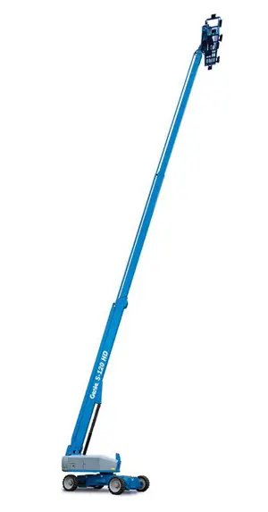
Genie Articulated Boom Lift SX-125 XC
Need answers fast?
Explore the manual using AI.
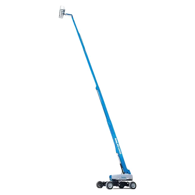
The Genie Articulated Boom Lift SX-125 XC is a versatile aerial work platform designed for enhanced reach and maneuverability in various industrial applications. Known for its robust performance and reliability, this boom lift is ideal for construction, maintenance, and other demanding tasks. Experience superior operational efficiency with Genie’s innovative engineering.
Turn manuals into instant answers
with your AI-powered assistantTurn manuals into instant answers
with your AI-powered assistant
Manual for Genie Articulated Boom Lift SX-125 XC
Complete asset maintenance, one click away
Get instant access to all the maintenance information you need. Empower technicians to perform preventive maintenance with asset packages, ready to use right out of the box.

Documents & Manuals
Find all the essential guides in one place.
 Tensioning Guide
- Belt-diagram
- C-120 pulleys
+ 13 more

Work Order Templates
Pre-built workflows to keep your asset running smoothly.
- Daily Electrical System Inspection
- Replace Roller and Pulley
- Install Engine B-120
+ 29 more

Procedures
Integrate maintenance plans directly into your work orders.
- Motion Industries
- Applied Industrial Technologies
- Electrical Brothers
+ 5 more

Parts
Access the parts list for your equipment in MaintainX.
- Drive Motor
- B2 Rollers
- Tensioning System
+ 40 more
Genie Articulated Boom Lift SX-125 XC
Create an account to install this asset package.
Maintenance Plans for Genie Articulated Boom Lift Model SX-125 XC
Integrate maintenance plans directly into your work orders in MaintainX.
1 Yearly Extendable Axle Inspection
Warning: Maintaining the axle wear pads in good condition is essential to safe machine operation.
Start the engine from the platform controls and extend the axles
Measure each axle wear pad
Is any wear pad less than specification?
If a wear pad is not less than specification, shim as necessary to obtain minimum clearance and no drag
Extend and retract the axles through the entire range of motion to check for tight spots that may cause binding or scraping of the axle tubes
Note: Always maintain squareness between the outer and inner axle tubes
Extendable axle wear pad Wear pad specifications : Minimum 0.4375 inch / 11.11 mm
Sign off on the axle inspection

3 Monthly Turntable Level Sensor Test
A properly functioning level sensor (SCON) is essential to safe machine operation. The ECM at the ground controls (CON) monitors the position and angle of the machine using the signal from the level sensor. The level sensor signal is used to control the maximum working height of the primary and secondary booms
A digital level will be required to perform this procedure
A kit is available through Genie Product Support (Genie part number 58351). This kit includes a digital level with a magnetic base and cable harnesses
A properly calibrated digital level is essential to proper machine calibration. Refer to the manufactures calibration information
Use the following chart to identify the description of each LCD screen control button used in this procedure
Perform this procedure with the booms in the fully stowed position and the axles fully extended
Place the machine on a firm surface that has a side slope greater than 2° (6.5 inches / 16.5 cm) but less than 5° (16 inches / 40.6 cm)
Place a digital level that has been calibrated to gravity on the X axis of the turntable
Turn the key switch to ground control and pull out the red Emergency Stop button to the on position at both ground and platform controls
Initial 50 Hours Boom Lift Maintenance
Inspect the Tires, Wheels and Lug Nut Torque
Grease the Turntable Rotation Bearing and Rotate Gear
Check the Turntable Rotation Bearing Bolts
Replace the Drive Hub Oil
Replace the Hydraulic Filters
Sign off on the boom lift maintenance
50 Hourly Track Tension Check
Warning: This procedure requires trained personnel with PPE!
Track assembly cleaned of any dirt, rocks, clay, etc.
Tracks chocked at one end of the machine to prevent rolling
Lifting jack of ample capacity (20,000 Ibs / 10,000 kg) centered under the drive chassis
Machine lifted until the tracks are off the ground and jack stands placed under the drive chassis for support
Visual inspection of the section of track under the bogey wheels performed
Grease plug on the track tension cylinder located and loosened
Grease zerk fitting on the other side of the track tension cylinder located
Grease pumped into the grease zerk fitting of the tension cylinder until grease, free from air, comes out of the grease plug
3 Monthly Oscillate Directional Valve Linkage Inspection
Drive chassis cover and axle covers removed from the non-steer end of the drive chassis
Oscillate directional valve located inside of the non-steer axle
Lock nut is tight against yoke
Yoke clevis pins are installed
Cotter pins are installed through clevis pins
Linkage is properly attached to directional valve
Sign off on the inspection
Parts for Genie Articulated Boom Lift SX-125 XC
Access the parts list for your equipment in MaintainX.
Digital Protractor
58377
O-ring Field Service Kit
49612
Digital Level Kit
58351
Digital Protractor
58377
O-ring Field Service Kit
49612
Digital Level Kit
58351
Digital Protractor
58377
O-ring Field Service Kit
49612
Digital Level Kit
58351
Unlock efficiency
with MaintainX CoPilot
MaintainX CoPilot is your expert colleague, on call 24/7, helping your team find the answers they need to keep equipment running.
Reduce Unplanned Downtime
Ensure your team follows consistent procedures to minimize equipment failures and costly delays.
Maximize Asset Availability
Keep your assets running longer and more reliably, with standardized maintenance workflows from OEM manuals.
Lower Maintenance Costs
Turn any technician into an expert to streamline operations, maintain more assets, and reduce overall costs.
Thousands of companies manage their assets with MaintainX

'%3e%3cpath%20fill='url(%23b)'%20d='M66.008%2080.068c-5.084-.786-9.763-3.834-12.442-8.68a16.942%2016.942%200%200%201-1.87-5.18c1.096.19%202.203.476%203.298.87%206.525%202.333%2010.836%207.68%2011.014%2012.99ZM51.47%2061.576c.488-5.524%203.62-10.716%208.847-13.597a17.132%2017.132%200%200%201%2011.335-1.882c-.798%208.145-7.43%2014.848-16.038%2015.599-1.417.119-2.799.07-4.144-.12Zm28.564-11.478a17.513%2017.513%200%200%201%203.727%204.62c4.608%208.335%201.584%2018.813-6.75%2023.409a16.988%2016.988%200%200%201-4.359%201.679%2019.624%2019.624%200%200%201-3.977-12.776c.346-7.561%204.942-13.931%2011.36-16.932Z'/%3e%3cpath%20fill='%23110F0D'%20fill-rule='evenodd'%20d='M142.831%2048.324h4.977V77.03h-4.977V48.324Zm27.278%2013.002c.322%201.048.453%202.263.453%203.62v12.073h-4.787V66.208c0-.75-.047-1.572-.154-2.143-.453-2.382-1.822-3.572-4.215-3.572-2.31%200-3.882%201.274-4.43%203.476-.143.596-.226%201.405-.226%202.25v10.8h-4.787V56.623h4.477v2.989c1.536-2.5%203.906-3.43%206.371-3.43%203.488%200%206.263%201.68%207.298%205.144Zm24.636%207.323c0%203.882-2.358%206.525-5.763%207.727-1.298.453-2.632.643-4.62.643h-10.169V48.324h9.085c1.691%200%203.156.143%204.049.38%203.465.93%205.727%203.68%205.727%207.335%200%202.441-.81%204.156-2.762%205.644%202.905%201.417%204.453%203.727%204.453%206.966Zm-15.634-8.656h4.584c1.024%200%201.917-.143%202.536-.417%201.215-.548%201.905-1.608%201.905-3.167%200-1.548-.643-2.572-1.845-3.132-.691-.31-1.762-.452-2.763-.452h-4.417v7.168Zm10.716%208.465c0-1.536-.893-3.37-3.227-3.893-.428-.095-1.036-.143-1.571-.143h-5.918v8.085h5.501c.56%200%201.429-.048%201.953-.167%201.94-.453%203.262-1.846%203.262-3.882Zm47.747-11.847-8.097%2020.408h-4.429l-8.109-20.408h5.191l5.192%2014.574%205.108-14.574h5.144Zm-20.218%2010.002c0%20.69-.036%201.262-.155%201.94h-15.943c.631%202.87%202.714%204.728%205.882%204.728%202.131%200%203.607-.882%204.703-2.525h4.87c-1.762%204.144-5.204%206.692-9.657%206.692-6.084%200-10.537-4.858-10.537-10.49%200-6.108%204.524-10.776%2010.335-10.776%206.239%200%2010.442%204.954%2010.502%2010.43Zm-4.763-1.405c-.333-2.846-2.643-4.858-5.691-4.858-2.894%200-5.287%201.929-5.621%204.858h11.312Zm-72.667%203.44c0%204.787-3.287%208.371-9.419%208.371H119.363V64.66c-1.917.274-3.87.69-5.811%201.238l4.537%2011.121h-5.418l-3.596-9.585c-5.144%202.084-10.085%205.216-14.217%209.585h-4.786L101.8%2048.312h4.56l5.68%2013.883a44.112%2044.112%200%200%201%207.323-1.774V48.312h9.084c1.703%200%203.156.143%204.061.393%203.453.929%205.727%203.667%205.727%207.323%200%201.917-.738%204.179-2.81%205.691%203.06%201.56%204.501%204.025%204.501%206.93Zm-15.634-8.667a62.664%2062.664%200%200%201%202.06-.036c1.703.012%203.239.131%204.608.37%201.441-.549%202.357-1.727%202.357-3.537%200-1.941-.881-3.144-2.488-3.667-.548-.18-1.358-.286-2.322-.286h-4.215v7.156Zm-16.55%203.905-3.715-9.894-6.394%2016.502c2.833-2.595%206.263-4.858%2010.109-6.608Zm27.254%204.74c0-2.775-3.131-4.347-8.513-4.418-.715%200-1.441.011-2.191.047v8.252h5.918c2.548%200%204.786-1.37%204.786-3.882Z'%20clip-rule='evenodd'/%3e%3c/g%3e%3cdefs%3e%3clinearGradient%20id='b'%20x1='51.47'%20x2='85.916'%20y1='62.946'%20y2='62.946'%20gradientUnits='userSpaceOnUse'%3e%3cstop%20stop-color='%23CD9F28'/%3e%3cstop%20offset='1'%20stop-color='%23ECD80B'/%3e%3c/linearGradient%3e%3cclipPath%20id='a'%3e%3cpath%20fill='%23fff'%20d='M51.47%2045.728h186.104V80.14H51.47z'/%3e%3c/clipPath%3e%3c/defs%3e%3c/svg%3e)


More from Genie


Explore Other Assets


© 2026 MaintainX. All rights reserved.