


Donaldson Donaldson Cartridge Dust Collector DWS 6-3 DWS 6-3
Need answers fast?
Explore the manual using AI.
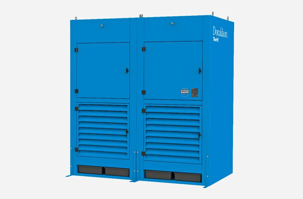
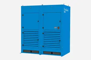
The Donaldson Cartridge Dust Collector DWS 6-3 is an industrial dust collection system designed for efficient air filtration and dust management. This model ensures optimal performance in various applications, providing reliable operation and maintaining air quality standards in industrial environments.
Turn manuals into instant answers
with your AI-powered assistantTurn manuals into instant answers
with your AI-powered assistant
Manual for Donaldson Donaldson Cartridge Dust Collector DWS 6-3 DWS 6-3
Complete asset maintenance, one click away
Get instant access to all the maintenance information you need. Empower technicians to perform preventive maintenance with asset packages, ready to use right out of the box.

Documents & Manuals
Find all the essential guides in one place.
 Tensioning Guide
- Belt-diagram
- C-120 pulleys
+ 13 more

Work Order Templates
Pre-built workflows to keep your asset running smoothly.
- Daily Electrical System Inspection
- Replace Roller and Pulley
- Install Engine B-120
+ 29 more

Procedures
Integrate maintenance plans directly into your work orders.
- Motion Industries
- Applied Industrial Technologies
- Electrical Brothers
+ 5 more

Parts
Access the parts list for your equipment in MaintainX.
- Drive Motor
- B2 Rollers
- Tensioning System
+ 40 more
Donaldson Donaldson Cartridge Dust Collector DWS 6-3 DWS 6-3
Create an account to install this asset package.
Maintenance Plans for Donaldson Donaldson Cartridge Dust Collector DWS 6-3 Model DWS 6-3
Integrate maintenance plans directly into your work orders in MaintainX.
Fluorescent Bulb Replacement
Light Fixture
Electrical work must be performed by a qualified electrician and comply with all applicable national and local codes.
Turn power off and lock out electrical power sources before performing service or maintenance work.
Do not install in classified hazardous atmospheres without an enclosure rated for the application.
- Industrial Light Fixture
This light fixture uses a wrap-around lens that is not fastened to the light housing by fasteners or latches.
To remove the lens: Lift lens one side at a time up and away from the housing.
To replace the bulbs: Rotate and remove from the rotary-lock lamp holders.
Replace with 40-watt, 48-inch long fluorescent bulbs.

Sprinkler Replacement
Sprinkler systems place a large quantity of water in the dust collector when activated. Provide adequate drainage to remove water. Excess water weight can cause the leg structure to collapse.
Optional fire control sprinklers are available for all models operating under negative pressure. Donaldson Torit supplied sprinklers require a minimum of 15 psig water pressure to each module. The volume of water discharged per sprinkler head is 20 gallons per minute.
Consult with local authorities when installing fire control systems on dust collection equipment.
1. Open the front access doors to access the sprinkler tap located in the dirty-air plenum.
2. Apply pipe sealant to the threads of the pipe reducer located on the sprinkler assembly.
3. Thread the sprinkler assembly onto the 1-inch diameter sprinkler tap.
4. Tighten securely.;
Photohelic Gauge Replacement
Warning: Electrical work must be performed by a qualified electrician and comply with all applicable national and local codes. Turn power off and lock out electrical power sources before performing service or maintenance work. Do not install in classified hazardous atmospheres without an enclosure rated for the application.
The Photohelic combines the functions of a differential pressure gauge and a pressure-based switch. The gauge function measures the pressure difference between the clean and ambient air and provides a visual display of filter condition. The low-pressure tap is located in the clean-air plenum on the back of the cabinet. The pressure-based switch function provides high-pressure ON and low-pressure OFF control of the filter cleaning system.
Choose a convenient, accessible location on or near the unit for mounting that provides the best visual advantage.
Mount the gauge to the remote panel or door using the mounting ring, retaining ring, and four #6-32 x 1 1/4-inch screws. Do not tighten screws. Connect one 1/8-inch NPT x 1/4-inch OD male adapter to the low-pressure port of the gauge. Align the adapter to the 2.375-inch hole in the right-hand side of the mounting bracket. Tighten screws.
Zero and maintain the gauge as directed in the manufacturer’s operating and maintenance instructions provided.
Sign off on the gauge replacement
IEC Control Panel Replacement
Warning: Electrical work must be performed by a qualified electrician and comply with all applicable national and local codes.
Turn power off and lock out electrical power sources before performing service or maintenance work.
Do not install in classified hazardous atmospheres without an enclosure rated for the application.
Control panel mounted in a convenient, accessible location
Tubing connected to the low-pressure barbed fitting on the control panel and to the barb fittings on the rear of the power module marked Low
Upload a photo of the control panel wired to the motor and solenoid valves
Blower motor turned on and off for rotation check
To reverse rotation with a three-phase power supply: Turn electrical power off at the source and switch any two leads on the output side of the blower-motor starter.
Compressed-air supply connected following the instructions in Compressed Air Installation
IEC Control Panel Inspection
IEC Control Panel with Programmable Logic Control
This control panel contains a safety disconnect switch, blower motor control, pulse control functions, and a Magnehelic gauge. The Programmable Logic Control, PLC, provides features such as sequential start-up, staggered aftershift cleaning, and troubleshooting capabilities.
Blower Control Functions
1. This control panel includes magnetic starters with a low-voltage control circuit.
2. The blower motor ON/OFF buttons are located on the control panel cover. A red blower motor RUNNING light is also provided.
3. Sequential start-up is provided for all DWS 4- and DWS 6-2, 3, and 4 modules. This allows a delay between starting each blower motor and reduces undesirable overload current at start-up.
4. The control panel has troubleshooting capabilities. If a blower motor shuts down due to a failure, such as an overload, the panel will flash the red RUNNING light quickly. The two amber lights, CLEANING and AFTERSHIFT CLEANING, will also flash indicating which circuit tripped the alarm.
For example: The overload on motor protector #3 is tripped. The red RUNNING light will flash quickly and the two amber lights, CLEANING and AFTERSHIFT CLEANING, will flash three times, then pause and repeat. This indicates that motor protector #3 has been tripped. The lights will continue to flash until the alarm is serviced.
5. Thermal overload relays and circuit breakers are provided for the motor circuit and fuses for the low voltage circuit. Standard voltages available are 208/230/460/575/60 Hz/3 phase.
Parts for Donaldson Donaldson Cartridge Dust Collector DWS 6-3 DWS 6-3
Access the parts list for your equipment in MaintainX.
Ultra-Web W/ EPDM Gasket
P031424-016-436
Ultra-Web NL SS
P032931-016-436
Ultra-Web FR
P191920-016-436
Fibra-Web W/ EPDM Gasket
P031585-016-431
Ultra-Web NL
P199474-016-436
Ultra-Web W/ EPDM Gasket
P031424-016-436
Ultra-Web NL SS
P032931-016-436
Ultra-Web FR
P191920-016-436
Fibra-Web W/ EPDM Gasket
P031585-016-431
Ultra-Web NL
P199474-016-436
Ultra-Web W/ EPDM Gasket
P031424-016-436
Ultra-Web NL SS
P032931-016-436
Ultra-Web FR
P191920-016-436
Fibra-Web W/ EPDM Gasket
P031585-016-431
Ultra-Web NL
P199474-016-436
Unlock efficiency
with MaintainX CoPilot
MaintainX CoPilot is your expert colleague, on call 24/7, helping your team find the answers they need to keep equipment running.
Reduce Unplanned Downtime
Ensure your team follows consistent procedures to minimize equipment failures and costly delays.
Maximize Asset Availability
Keep your assets running longer and more reliably, with standardized maintenance workflows from OEM manuals.
Lower Maintenance Costs
Turn any technician into an expert to streamline operations, maintain more assets, and reduce overall costs.
Thousands of companies manage their assets with MaintainX

'%3e%3cpath%20fill='url(%23b)'%20d='M66.008%2080.068c-5.084-.786-9.763-3.834-12.442-8.68a16.942%2016.942%200%200%201-1.87-5.18c1.096.19%202.203.476%203.298.87%206.525%202.333%2010.836%207.68%2011.014%2012.99ZM51.47%2061.576c.488-5.524%203.62-10.716%208.847-13.597a17.132%2017.132%200%200%201%2011.335-1.882c-.798%208.145-7.43%2014.848-16.038%2015.599-1.417.119-2.799.07-4.144-.12Zm28.564-11.478a17.513%2017.513%200%200%201%203.727%204.62c4.608%208.335%201.584%2018.813-6.75%2023.409a16.988%2016.988%200%200%201-4.359%201.679%2019.624%2019.624%200%200%201-3.977-12.776c.346-7.561%204.942-13.931%2011.36-16.932Z'/%3e%3cpath%20fill='%23110F0D'%20fill-rule='evenodd'%20d='M142.831%2048.324h4.977V77.03h-4.977V48.324Zm27.278%2013.002c.322%201.048.453%202.263.453%203.62v12.073h-4.787V66.208c0-.75-.047-1.572-.154-2.143-.453-2.382-1.822-3.572-4.215-3.572-2.31%200-3.882%201.274-4.43%203.476-.143.596-.226%201.405-.226%202.25v10.8h-4.787V56.623h4.477v2.989c1.536-2.5%203.906-3.43%206.371-3.43%203.488%200%206.263%201.68%207.298%205.144Zm24.636%207.323c0%203.882-2.358%206.525-5.763%207.727-1.298.453-2.632.643-4.62.643h-10.169V48.324h9.085c1.691%200%203.156.143%204.049.38%203.465.93%205.727%203.68%205.727%207.335%200%202.441-.81%204.156-2.762%205.644%202.905%201.417%204.453%203.727%204.453%206.966Zm-15.634-8.656h4.584c1.024%200%201.917-.143%202.536-.417%201.215-.548%201.905-1.608%201.905-3.167%200-1.548-.643-2.572-1.845-3.132-.691-.31-1.762-.452-2.763-.452h-4.417v7.168Zm10.716%208.465c0-1.536-.893-3.37-3.227-3.893-.428-.095-1.036-.143-1.571-.143h-5.918v8.085h5.501c.56%200%201.429-.048%201.953-.167%201.94-.453%203.262-1.846%203.262-3.882Zm47.747-11.847-8.097%2020.408h-4.429l-8.109-20.408h5.191l5.192%2014.574%205.108-14.574h5.144Zm-20.218%2010.002c0%20.69-.036%201.262-.155%201.94h-15.943c.631%202.87%202.714%204.728%205.882%204.728%202.131%200%203.607-.882%204.703-2.525h4.87c-1.762%204.144-5.204%206.692-9.657%206.692-6.084%200-10.537-4.858-10.537-10.49%200-6.108%204.524-10.776%2010.335-10.776%206.239%200%2010.442%204.954%2010.502%2010.43Zm-4.763-1.405c-.333-2.846-2.643-4.858-5.691-4.858-2.894%200-5.287%201.929-5.621%204.858h11.312Zm-72.667%203.44c0%204.787-3.287%208.371-9.419%208.371H119.363V64.66c-1.917.274-3.87.69-5.811%201.238l4.537%2011.121h-5.418l-3.596-9.585c-5.144%202.084-10.085%205.216-14.217%209.585h-4.786L101.8%2048.312h4.56l5.68%2013.883a44.112%2044.112%200%200%201%207.323-1.774V48.312h9.084c1.703%200%203.156.143%204.061.393%203.453.929%205.727%203.667%205.727%207.323%200%201.917-.738%204.179-2.81%205.691%203.06%201.56%204.501%204.025%204.501%206.93Zm-15.634-8.667a62.664%2062.664%200%200%201%202.06-.036c1.703.012%203.239.131%204.608.37%201.441-.549%202.357-1.727%202.357-3.537%200-1.941-.881-3.144-2.488-3.667-.548-.18-1.358-.286-2.322-.286h-4.215v7.156Zm-16.55%203.905-3.715-9.894-6.394%2016.502c2.833-2.595%206.263-4.858%2010.109-6.608Zm27.254%204.74c0-2.775-3.131-4.347-8.513-4.418-.715%200-1.441.011-2.191.047v8.252h5.918c2.548%200%204.786-1.37%204.786-3.882Z'%20clip-rule='evenodd'/%3e%3c/g%3e%3cdefs%3e%3clinearGradient%20id='b'%20x1='51.47'%20x2='85.916'%20y1='62.946'%20y2='62.946'%20gradientUnits='userSpaceOnUse'%3e%3cstop%20stop-color='%23CD9F28'/%3e%3cstop%20offset='1'%20stop-color='%23ECD80B'/%3e%3c/linearGradient%3e%3cclipPath%20id='a'%3e%3cpath%20fill='%23fff'%20d='M51.47%2045.728h186.104V80.14H51.47z'/%3e%3c/clipPath%3e%3c/defs%3e%3c/svg%3e)


More from Donaldson


Explore Other Assets


© 2025 MaintainX. All rights reserved.