


Donaldson Donaldson Cartridge Dust Collector DWS 6-2 DWS 6-2
Need answers fast?
Explore the manual using AI.
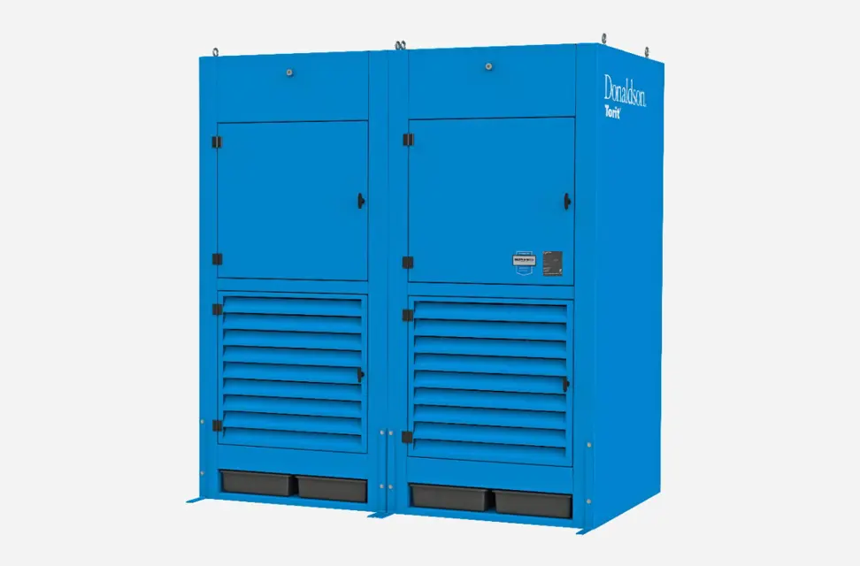
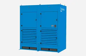
The Donaldson Cartridge Dust Collector DWS 6-2 is a high-efficiency industrial dust collection system designed to capture airborne particles and improve air quality. This reliable equipment is essential for maintaining a safe and clean working environment in various manufacturing processes.
Turn manuals into instant answers
with your AI-powered assistantTurn manuals into instant answers
with your AI-powered assistant
Manual for Donaldson Donaldson Cartridge Dust Collector DWS 6-2 DWS 6-2
Complete asset maintenance, one click away
Get instant access to all the maintenance information you need. Empower technicians to perform preventive maintenance with asset packages, ready to use right out of the box.

Documents & Manuals
Find all the essential guides in one place.
 Tensioning Guide
- Belt-diagram
- C-120 pulleys
+ 13 more

Work Order Templates
Pre-built workflows to keep your asset running smoothly.
- Daily Electrical System Inspection
- Replace Roller and Pulley
- Install Engine B-120
+ 29 more

Procedures
Integrate maintenance plans directly into your work orders.
- Motion Industries
- Applied Industrial Technologies
- Electrical Brothers
+ 5 more

Parts
Access the parts list for your equipment in MaintainX.
- Drive Motor
- B2 Rollers
- Tensioning System
+ 40 more
Donaldson Donaldson Cartridge Dust Collector DWS 6-2 DWS 6-2
Create an account to install this asset package.
Maintenance Plans for Donaldson Donaldson Cartridge Dust Collector DWS 6-2 Model DWS 6-2
Integrate maintenance plans directly into your work orders in MaintainX.
Cartridge Dust Collector Operational Checklist
Instruct all personnel on safe use and maintenance procedures.
Use proper equipment and adopt all safety precautions needed for servicing equipment. Electrical service or maintenance work must be performed by a qualified electrician and comply with all applicable national and local codes.
Turn power off and lock out electrical power sources before performing service or maintenance work.
Do not install in classified hazardous atmospheres without an enclosure rated for the application.
Turn compressed air supply off and bleed lines before performing service or maintenance work.
Do not set compressed-air pressure above 50 psig. Component damage can occur.
All compressed air components must be sized to meet the maximum system requirements of 60 psig supply pressure.
The compressed-air supply must be oil and moisture free. Contamination in the compressed air used to clean filters will result in poor cleaning, cleaning valve failure, or poor collector performance.
Purge compressed air lines to remove debris before connecting to the unit’s compressed air manifold.

IEC Control Panel Replacement
Warning: Electrical work must be performed by a qualified electrician and comply with all applicable national and local codes.
Turn power off and lock out electrical power sources before performing service or maintenance work.
Do not install in classified hazardous atmospheres without an enclosure rated for the application.
Control panel mounted in a convenient, accessible location
Tubing connected to the low-pressure barbed fitting on the control panel and to the barb fittings on the rear of the power module marked Low
Upload a photo of the control panel wired to the motor and solenoid valves
Blower motor turned on and off for rotation check
To reverse rotation with a three-phase power supply: Turn electrical power off at the source and switch any two leads on the output side of the blower-motor starter.
Compressed-air supply connected following the instructions in Compressed Air Installation
IEC Control Panel Inspection
Warning: This inspection requires trained personnel with PPE!
Safety disconnect switch functional?
Blower motor control functional?
Pulse control functions operational?
Magnehelic gauge functional?
Programmable Logic Control (PLC) functional?
Sequential start-up feature operational?
Troubleshooting capabilities functional?
Thermal overload relays and circuit breakers functional?
Magnehelic Gauge Replacement
Warning: This procedure requires trained personnel with PPE!
Choose a location for mounting
Pressure ports on the back of the gauge plugged
1/8-inch NPT male adapter installed into the low-pressure port
Mounting bracket attached using three #6-32 x 1/4-inch screws
Gauge and bracket assembly mounted to the supporting structure using three self-drilling screws
Gauge zeroed and maintained as directed in the manufacturer’s operating and maintenance instructions
Sign off on the Magnehelic Gauge Replacement
Photohelic Gauge Replacement
Warning: Electrical work must be performed by a qualified electrician and comply with all applicable national and local codes. Turn power off and lock out electrical power sources before performing service or maintenance work. Do not install in classified hazardous atmospheres without an enclosure rated for the application.
The Photohelic combines the functions of a differential pressure gauge and a pressure-based switch. The gauge function measures the pressure difference between the clean and ambient air and provides a visual display of filter condition. The low-pressure tap is located in the clean-air plenum on the back of the cabinet. The pressure-based switch function provides high-pressure ON and low-pressure OFF control of the filter cleaning system.
Choose a convenient, accessible location on or near the unit for mounting that provides the best visual advantage.
Mount the gauge to the remote panel or door using the mounting ring, retaining ring, and four #6-32 x 1 1/4-inch screws. Do not tighten screws. Connect one 1/8-inch NPT x 1/4-inch OD male adapter to the low-pressure port of the gauge. Align the adapter to the 2.375-inch hole in the right-hand side of the mounting bracket. Tighten screws.
Zero and maintain the gauge as directed in the manufacturer’s operating and maintenance instructions provided.
Sign off on the gauge replacement
Parts for Donaldson Donaldson Cartridge Dust Collector DWS 6-2 DWS 6-2
Access the parts list for your equipment in MaintainX.
Ultra-Tek
P199476-016-426
Ultra-Web SB W/ High Temp Gasket/Potting
P033086-016-436
Ultra-Web
P191889-016-436
Ultra-Web SB
P031791-016-436
Fibra-Web SS
P199611-016-431
Ultra-Tek
P199476-016-426
Ultra-Web SB W/ High Temp Gasket/Potting
P033086-016-436
Ultra-Web
P191889-016-436
Ultra-Web SB
P031791-016-436
Fibra-Web SS
P199611-016-431
Ultra-Tek
P199476-016-426
Ultra-Web SB W/ High Temp Gasket/Potting
P033086-016-436
Ultra-Web
P191889-016-436
Ultra-Web SB
P031791-016-436
Fibra-Web SS
P199611-016-431
Unlock efficiency
with MaintainX CoPilot
MaintainX CoPilot is your expert colleague, on call 24/7, helping your team find the answers they need to keep equipment running.
Reduce Unplanned Downtime
Ensure your team follows consistent procedures to minimize equipment failures and costly delays.
Maximize Asset Availability
Keep your assets running longer and more reliably, with standardized maintenance workflows from OEM manuals.
Lower Maintenance Costs
Turn any technician into an expert to streamline operations, maintain more assets, and reduce overall costs.
Thousands of companies manage their assets with MaintainX

'%3e%3cpath%20fill='url(%23b)'%20d='M66.008%2080.068c-5.084-.786-9.763-3.834-12.442-8.68a16.942%2016.942%200%200%201-1.87-5.18c1.096.19%202.203.476%203.298.87%206.525%202.333%2010.836%207.68%2011.014%2012.99ZM51.47%2061.576c.488-5.524%203.62-10.716%208.847-13.597a17.132%2017.132%200%200%201%2011.335-1.882c-.798%208.145-7.43%2014.848-16.038%2015.599-1.417.119-2.799.07-4.144-.12Zm28.564-11.478a17.513%2017.513%200%200%201%203.727%204.62c4.608%208.335%201.584%2018.813-6.75%2023.409a16.988%2016.988%200%200%201-4.359%201.679%2019.624%2019.624%200%200%201-3.977-12.776c.346-7.561%204.942-13.931%2011.36-16.932Z'/%3e%3cpath%20fill='%23110F0D'%20fill-rule='evenodd'%20d='M142.831%2048.324h4.977V77.03h-4.977V48.324Zm27.278%2013.002c.322%201.048.453%202.263.453%203.62v12.073h-4.787V66.208c0-.75-.047-1.572-.154-2.143-.453-2.382-1.822-3.572-4.215-3.572-2.31%200-3.882%201.274-4.43%203.476-.143.596-.226%201.405-.226%202.25v10.8h-4.787V56.623h4.477v2.989c1.536-2.5%203.906-3.43%206.371-3.43%203.488%200%206.263%201.68%207.298%205.144Zm24.636%207.323c0%203.882-2.358%206.525-5.763%207.727-1.298.453-2.632.643-4.62.643h-10.169V48.324h9.085c1.691%200%203.156.143%204.049.38%203.465.93%205.727%203.68%205.727%207.335%200%202.441-.81%204.156-2.762%205.644%202.905%201.417%204.453%203.727%204.453%206.966Zm-15.634-8.656h4.584c1.024%200%201.917-.143%202.536-.417%201.215-.548%201.905-1.608%201.905-3.167%200-1.548-.643-2.572-1.845-3.132-.691-.31-1.762-.452-2.763-.452h-4.417v7.168Zm10.716%208.465c0-1.536-.893-3.37-3.227-3.893-.428-.095-1.036-.143-1.571-.143h-5.918v8.085h5.501c.56%200%201.429-.048%201.953-.167%201.94-.453%203.262-1.846%203.262-3.882Zm47.747-11.847-8.097%2020.408h-4.429l-8.109-20.408h5.191l5.192%2014.574%205.108-14.574h5.144Zm-20.218%2010.002c0%20.69-.036%201.262-.155%201.94h-15.943c.631%202.87%202.714%204.728%205.882%204.728%202.131%200%203.607-.882%204.703-2.525h4.87c-1.762%204.144-5.204%206.692-9.657%206.692-6.084%200-10.537-4.858-10.537-10.49%200-6.108%204.524-10.776%2010.335-10.776%206.239%200%2010.442%204.954%2010.502%2010.43Zm-4.763-1.405c-.333-2.846-2.643-4.858-5.691-4.858-2.894%200-5.287%201.929-5.621%204.858h11.312Zm-72.667%203.44c0%204.787-3.287%208.371-9.419%208.371H119.363V64.66c-1.917.274-3.87.69-5.811%201.238l4.537%2011.121h-5.418l-3.596-9.585c-5.144%202.084-10.085%205.216-14.217%209.585h-4.786L101.8%2048.312h4.56l5.68%2013.883a44.112%2044.112%200%200%201%207.323-1.774V48.312h9.084c1.703%200%203.156.143%204.061.393%203.453.929%205.727%203.667%205.727%207.323%200%201.917-.738%204.179-2.81%205.691%203.06%201.56%204.501%204.025%204.501%206.93Zm-15.634-8.667a62.664%2062.664%200%200%201%202.06-.036c1.703.012%203.239.131%204.608.37%201.441-.549%202.357-1.727%202.357-3.537%200-1.941-.881-3.144-2.488-3.667-.548-.18-1.358-.286-2.322-.286h-4.215v7.156Zm-16.55%203.905-3.715-9.894-6.394%2016.502c2.833-2.595%206.263-4.858%2010.109-6.608Zm27.254%204.74c0-2.775-3.131-4.347-8.513-4.418-.715%200-1.441.011-2.191.047v8.252h5.918c2.548%200%204.786-1.37%204.786-3.882Z'%20clip-rule='evenodd'/%3e%3c/g%3e%3cdefs%3e%3clinearGradient%20id='b'%20x1='51.47'%20x2='85.916'%20y1='62.946'%20y2='62.946'%20gradientUnits='userSpaceOnUse'%3e%3cstop%20stop-color='%23CD9F28'/%3e%3cstop%20offset='1'%20stop-color='%23ECD80B'/%3e%3c/linearGradient%3e%3cclipPath%20id='a'%3e%3cpath%20fill='%23fff'%20d='M51.47%2045.728h186.104V80.14H51.47z'/%3e%3c/clipPath%3e%3c/defs%3e%3c/svg%3e)


More from Donaldson


Explore Other Assets


© 2025 MaintainX. All rights reserved.