


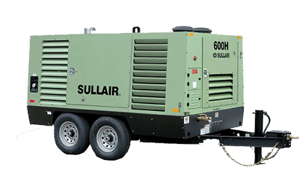
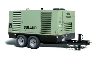
Sullair Portable Air Compressor 600H
Need answers fast?
Explore the manual using AI.
Turn manuals into instant answers
with your AI-powered assistantTurn manuals into instant answers
with your AI-powered assistant
Complete asset maintenance, one click away
Get instant access to all the maintenance information you need. Empower technicians to perform preventive maintenance with asset packages, ready to use right out of the box.

Documents & Manuals
Find all the essential guides in one place.
 Tensioning Guide
- Belt-diagram
- C-120 pulleys
+ 13 more

Work Order Templates
Pre-built workflows to keep your asset running smoothly.
- Daily Electrical System Inspection
- Replace Roller and Pulley
- Install Engine B-120
+ 29 more

Procedures
Integrate maintenance plans directly into your work orders.
- Motion Industries
- Applied Industrial Technologies
- Electrical Brothers
+ 5 more

Parts
Access the parts list for your equipment in MaintainX.
- Drive Motor
- B2 Rollers
- Tensioning System
+ 40 more
Sullair Portable Air Compressor 600H
Create an account to install this asset package.
Maintenance Plans for Sullair Portable Air Compressor Model 600H
Integrate maintenance plans directly into your work orders in MaintainX.
Separator Element Replacement
Refer to Figure 5-6. When fluid carry-over is evident after the fluid return-line strainer and orifice, as well as the blowdown valve diaphragm, have been inspected and found to be in satisfactory condition, or if the separator restriction gauge reads in excess of 10 psig (0.7 bar), separator element replacement is necessary.
Remove all piping connected to the receiver tank cover to allow removal (return line, service line, etc.)
Remove the fluid return line from the fitting in the cover.
Remove the twelve (12) 5/8 x 2.25 in cap-screws and lock washers and lift the cover from the receiver tank with the minimum pressure/check valve in place.
Remove the separator element.
Scrape the old gasket material from the cover and the flange on the receiver tank. Be sure to keep all scrapings from falling inside the tank.
Install the gaskets.
Make sure grounding staples are attached to separator gasket. DO NOT REMOVE STAPLES.
Replace the receiver tank cover. Install the twelve (12) 5/8 x 2.25 in capscrews and lock washers in finger-tight, then gradually tighten in a crisscross pattern in 4 to 5 steps.; Always tighten the capscrews alternately at opposite sides of the cover. Never tighten capscrews adjacent to each other. Torque capscrews to 112 to 127 ft.lbs (151 to 172 N-m).

300 Hourly Compressor Maintenance
5.7 Maintenance every 300 hours
When not using Sullair AWF®, change the compressor fluid and replace the fluid filter element. Refer to Main Fluid Filter Servicing on page 62.
5.11.4 Main fluid filter servicing
Refer to Figure 5-3. The main fluid filters are located schematically in the coolant line between the receiver tank and the compressor unit. The main filter elements are replaceable. For installation of the filter elements, follow the procedure explained below:
1. The compressor MUST be shut off and system pressure MUST be relieved.
2. Position a suitable container beneath the elements to catch fluid drainage.
3. Remove elements using a suitable tool.
4. Rotate each element counterclockwise to remove.
5. Remove element and discard. These elements are not cleanable.
1000 Hourly Compressor Maintenance
Maintenance every 1000 hours
Clean the return line orifice and strainer
Repack the wheel bearings on wheel-mounted units
Sign off on the 1000 hourly compressor maintenance
Engine Coolant Maintenance
Warning: Only use the recommended coolant for the machine. Do not mix different color coolants.
Select the color of the coolant used
Is the coolant the same as what is in the cooling system?
If unsure of the coolant type, flush the system until the flushed water is clear.
Has the system been flushed?
Select the type of coolant to be used
CAUTION: The radiator and engine cooling system must be drained and flushed periodically.
Enter the hours since the last coolant change
Dispose of fluids in accordance with applicable federal, state and local regulations.
1500 Hourly Compressor Maintenance
Maintenance every 1500 hours
Is Sullair AWF® used?
If Sullair AWF® is used, proceed with the following steps
Compressor fluid change procedure
Has the compressor been warmed up for 5 to 10 minutes?
Is the compressor off and all internal pressure relieved?
Has the fluid been drained by opening the appropriate drain valve?
Has the valve been closed after draining?
Has the compressor fluid been changed and the fluid filter element replaced?
Parts for Sullair Portable Air Compressor 600H
Access the parts list for your equipment in MaintainX.
Multi-Viscosity Lubricant, 55 Gallons, 208 Liter Drum
250030-758
Multi-Viscosity Lubricant, 5 Gallons/18.9 Liters
250030-757
Repair Kit For Thermostat Element
02250087-682
Replacement Filter Element
250025-526
Primary Filter Element
048462
Multi-Viscosity Lubricant, 55 Gallons, 208 Liter Drum
250030-758
Multi-Viscosity Lubricant, 5 Gallons/18.9 Liters
250030-757
Repair Kit For Thermostat Element
02250087-682
Replacement Filter Element
250025-526
Primary Filter Element
048462
Multi-Viscosity Lubricant, 55 Gallons, 208 Liter Drum
250030-758
Multi-Viscosity Lubricant, 5 Gallons/18.9 Liters
250030-757
Repair Kit For Thermostat Element
02250087-682
Replacement Filter Element
250025-526
Primary Filter Element
048462
Unlock efficiency
with MaintainX CoPilot
MaintainX CoPilot is your expert colleague, on call 24/7, helping your team find the answers they need to keep equipment running.
Reduce Unplanned Downtime
Ensure your team follows consistent procedures to minimize equipment failures and costly delays.
Maximize Asset Availability
Keep your assets running longer and more reliably, with standardized maintenance workflows from OEM manuals.
Lower Maintenance Costs
Turn any technician into an expert to streamline operations, maintain more assets, and reduce overall costs.
Thousands of companies manage their assets with MaintainX

'%3e%3cpath%20fill='url(%23b)'%20d='M66.008%2080.068c-5.084-.786-9.763-3.834-12.442-8.68a16.942%2016.942%200%200%201-1.87-5.18c1.096.19%202.203.476%203.298.87%206.525%202.333%2010.836%207.68%2011.014%2012.99ZM51.47%2061.576c.488-5.524%203.62-10.716%208.847-13.597a17.132%2017.132%200%200%201%2011.335-1.882c-.798%208.145-7.43%2014.848-16.038%2015.599-1.417.119-2.799.07-4.144-.12Zm28.564-11.478a17.513%2017.513%200%200%201%203.727%204.62c4.608%208.335%201.584%2018.813-6.75%2023.409a16.988%2016.988%200%200%201-4.359%201.679%2019.624%2019.624%200%200%201-3.977-12.776c.346-7.561%204.942-13.931%2011.36-16.932Z'/%3e%3cpath%20fill='%23110F0D'%20fill-rule='evenodd'%20d='M142.831%2048.324h4.977V77.03h-4.977V48.324Zm27.278%2013.002c.322%201.048.453%202.263.453%203.62v12.073h-4.787V66.208c0-.75-.047-1.572-.154-2.143-.453-2.382-1.822-3.572-4.215-3.572-2.31%200-3.882%201.274-4.43%203.476-.143.596-.226%201.405-.226%202.25v10.8h-4.787V56.623h4.477v2.989c1.536-2.5%203.906-3.43%206.371-3.43%203.488%200%206.263%201.68%207.298%205.144Zm24.636%207.323c0%203.882-2.358%206.525-5.763%207.727-1.298.453-2.632.643-4.62.643h-10.169V48.324h9.085c1.691%200%203.156.143%204.049.38%203.465.93%205.727%203.68%205.727%207.335%200%202.441-.81%204.156-2.762%205.644%202.905%201.417%204.453%203.727%204.453%206.966Zm-15.634-8.656h4.584c1.024%200%201.917-.143%202.536-.417%201.215-.548%201.905-1.608%201.905-3.167%200-1.548-.643-2.572-1.845-3.132-.691-.31-1.762-.452-2.763-.452h-4.417v7.168Zm10.716%208.465c0-1.536-.893-3.37-3.227-3.893-.428-.095-1.036-.143-1.571-.143h-5.918v8.085h5.501c.56%200%201.429-.048%201.953-.167%201.94-.453%203.262-1.846%203.262-3.882Zm47.747-11.847-8.097%2020.408h-4.429l-8.109-20.408h5.191l5.192%2014.574%205.108-14.574h5.144Zm-20.218%2010.002c0%20.69-.036%201.262-.155%201.94h-15.943c.631%202.87%202.714%204.728%205.882%204.728%202.131%200%203.607-.882%204.703-2.525h4.87c-1.762%204.144-5.204%206.692-9.657%206.692-6.084%200-10.537-4.858-10.537-10.49%200-6.108%204.524-10.776%2010.335-10.776%206.239%200%2010.442%204.954%2010.502%2010.43Zm-4.763-1.405c-.333-2.846-2.643-4.858-5.691-4.858-2.894%200-5.287%201.929-5.621%204.858h11.312Zm-72.667%203.44c0%204.787-3.287%208.371-9.419%208.371H119.363V64.66c-1.917.274-3.87.69-5.811%201.238l4.537%2011.121h-5.418l-3.596-9.585c-5.144%202.084-10.085%205.216-14.217%209.585h-4.786L101.8%2048.312h4.56l5.68%2013.883a44.112%2044.112%200%200%201%207.323-1.774V48.312h9.084c1.703%200%203.156.143%204.061.393%203.453.929%205.727%203.667%205.727%207.323%200%201.917-.738%204.179-2.81%205.691%203.06%201.56%204.501%204.025%204.501%206.93Zm-15.634-8.667a62.664%2062.664%200%200%201%202.06-.036c1.703.012%203.239.131%204.608.37%201.441-.549%202.357-1.727%202.357-3.537%200-1.941-.881-3.144-2.488-3.667-.548-.18-1.358-.286-2.322-.286h-4.215v7.156Zm-16.55%203.905-3.715-9.894-6.394%2016.502c2.833-2.595%206.263-4.858%2010.109-6.608Zm27.254%204.74c0-2.775-3.131-4.347-8.513-4.418-.715%200-1.441.011-2.191.047v8.252h5.918c2.548%200%204.786-1.37%204.786-3.882Z'%20clip-rule='evenodd'/%3e%3c/g%3e%3cdefs%3e%3clinearGradient%20id='b'%20x1='51.47'%20x2='85.916'%20y1='62.946'%20y2='62.946'%20gradientUnits='userSpaceOnUse'%3e%3cstop%20stop-color='%23CD9F28'/%3e%3cstop%20offset='1'%20stop-color='%23ECD80B'/%3e%3c/linearGradient%3e%3cclipPath%20id='a'%3e%3cpath%20fill='%23fff'%20d='M51.47%2045.728h186.104V80.14H51.47z'/%3e%3c/clipPath%3e%3c/defs%3e%3c/svg%3e)


More from Sullair


Explore Other Assets


© 2026 MaintainX. All rights reserved.