


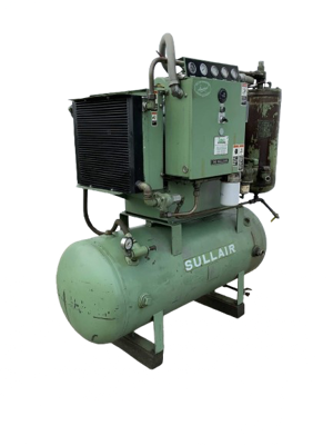
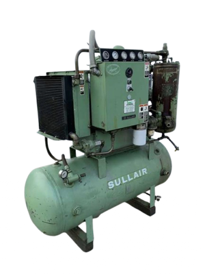
Sullair Air-Cooled Compressor 10B 25HP-251335-003 AC
Need answers fast?
Explore the manual using AI.
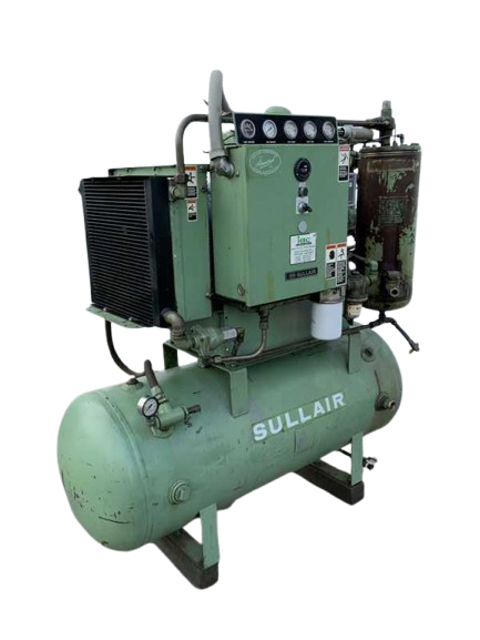
The Sullair Air-Cooled Compressor 10B 25HP-251335-003 AC is a reliable industrial compressor designed for efficient air delivery. Known for its durability and performance, this model is ideal for various applications requiring consistent compressed air supply. Regular maintenance ensures optimal functionality and longevity.
Turn manuals into instant answers
with your AI-powered assistantTurn manuals into instant answers
with your AI-powered assistant
Complete asset maintenance, one click away
Get instant access to all the maintenance information you need. Empower technicians to perform preventive maintenance with asset packages, ready to use right out of the box.

Documents & Manuals
Find all the essential guides in one place.
 Tensioning Guide
- Belt-diagram
- C-120 pulleys
+ 13 more

Work Order Templates
Pre-built workflows to keep your asset running smoothly.
- Daily Electrical System Inspection
- Replace Roller and Pulley
- Install Engine B-120
+ 29 more

Procedures
Integrate maintenance plans directly into your work orders.
- Motion Industries
- Applied Industrial Technologies
- Electrical Brothers
+ 5 more

Parts
Access the parts list for your equipment in MaintainX.
- Drive Motor
- B2 Rollers
- Tensioning System
+ 40 more
Sullair Air-Cooled Compressor 10B 25HP-251335-003 AC
Create an account to install this asset package.
Maintenance Plans for Sullair Air-Cooled Compressor Model 10B 25HP-251335-003 AC
Integrate maintenance plans directly into your work orders in MaintainX.
Compressor Control System Maintenance
Warning: This procedure requires trained personnel with PPE!
Adjust Control System with a desired operating range of 115 to 125 PSIG (792 to 862kPa). Differential is the difference between the high and low pressure settings. 10 PSIG (7kPa) is typical
Remove cover to pressure switch
Turn the range adjusting screw to the high pressure setting. Turning the screw counterclock-wise lowers both the high and low pressure equally
Differential is the difference between the high and low pressure settings. 10 PSIG (7kPa) is typical
Turn the differential adjusting screw to the lower (reset) setting. Turning the screw counterclock- wise widens the differential by lowering the reset (lower) setting only
When the pressure switch adjustment is complete, the pressure regulator should be adjusted for the pressure at which modulation of air delivery should begin. In this case that pressure will be 118 PSIG (824kPa). The regulator is adjusted by loosening the jam nut on the end of the cone shaped cover of the pressure regulator. When the jam nut is loose, turn the adjusting screw clockwise to increase or counterclockwise to decrease the setting
To set the regulator, continue closing the service valve, until the line pressure is 118 PSIG (824kPa). At this point regulator should pass a signal to the inlet valve to start closing it. If the line pressure keeps on rising or if the modulation does not begin, adjust the regulator valve as de- scribed above. After adjustment line pressure should be approximately 118 PSIG (824kPa) and 1.00 in. Hg vacuum below the inlet
Now close the service valve, line pressure will start rising. When line pressure reaches 125 lbs., the inlet valve will be closed to its maximum position. The inlet vacuum at this point will be around 25 in. Hg. The machine should unload at this point

Compressor Thermal Valve Maintenance
Warning: This maintenance check requires trained personnel with PPE!
Remove the appropriate piping from the thermal valve housing
Remove the four (4) capscrews holding the housing together and separate the upper housing from the lower housing
Remove element
Remove and replace the element seal in the upper housing
Remove and replace the o-ring between the upper and lower housings
Replace element
Re-assemble the housing
Sign off on the thermal valve maintenance
6 Monthly Air Filter Element Inspection
Place a bright light inside the element to inspect for damage or leak holes. Concentrated light will shine through the element and disclose any holes
Inspect all gaskets and gasket contact surfaces of the housing. Should faulty gaskets be evident, correct the condition immediately
If the clean element is to be stored for later use, it must be stored in a clean container
After the element has been installed, inspect and tighten all air inlet connections prior to resuming operation
Sign off on the air filter element inspection
Compressor Pressure Regulator Valve Maintenance
Repair pressure regulator valve 250017-280, use repair kit 250019-453
Loosen the locknut and turn the adjusting screw counterclockwise until the inner spring tension is relieved. The adjusting screw should turn freely when the spring tension is relieved
Remove the spring chamber from the body to allow access to internal parts
Remove the spring button and the spring. The dampener will stay inside the spring as it is removed. Leave the dampener inside the spring as there is no need to remove it
After removing the spring, remove the gasket stop and brass gasket
Remove the pressure plate nut and disassemble the pressure plate, diaphragm, diaphragm gasket (rubberized asbestos), seat disc and seat gasket
Remove and discard the seat ring
Reassemble the regulator using the new parts provided in the repair kit
Reassemble the diaphragm, pressure plate, gasket, seat disc, and seat disc gasket and tighten the nut. All of these parts with the exception of the pressure plate are provided in the repair kit
Compressor Coil Maintenance
Enter the part number of the coil
Retaining clip removed
Yoke containing the coil and sleeves slipped off the solenoid base sub-assembly
Reassembled in reverse order of disassembly
Sign off on the compressor coil maintenance
Parts for Sullair Air-Cooled Compressor 10B 25HP-251335-003 AC
Access the parts list for your equipment in MaintainX.
Air Inlet Valve
250025–654
Flexible Coupling
040033
Repair Kit
250025–621
Element
250025–525
Air Filter
0410036
Air Inlet Valve
250025–654
Flexible Coupling
040033
Repair Kit
250025–621
Element
250025–525
Air Filter
0410036
Air Inlet Valve
250025–654
Flexible Coupling
040033
Repair Kit
250025–621
Element
250025–525
Air Filter
0410036
Unlock efficiency
with MaintainX CoPilot
MaintainX CoPilot is your expert colleague, on call 24/7, helping your team find the answers they need to keep equipment running.
Reduce Unplanned Downtime
Ensure your team follows consistent procedures to minimize equipment failures and costly delays.
Maximize Asset Availability
Keep your assets running longer and more reliably, with standardized maintenance workflows from OEM manuals.
Lower Maintenance Costs
Turn any technician into an expert to streamline operations, maintain more assets, and reduce overall costs.
Thousands of companies manage their assets with MaintainX

'%3e%3cpath%20fill='url(%23b)'%20d='M66.008%2080.068c-5.084-.786-9.763-3.834-12.442-8.68a16.942%2016.942%200%200%201-1.87-5.18c1.096.19%202.203.476%203.298.87%206.525%202.333%2010.836%207.68%2011.014%2012.99ZM51.47%2061.576c.488-5.524%203.62-10.716%208.847-13.597a17.132%2017.132%200%200%201%2011.335-1.882c-.798%208.145-7.43%2014.848-16.038%2015.599-1.417.119-2.799.07-4.144-.12Zm28.564-11.478a17.513%2017.513%200%200%201%203.727%204.62c4.608%208.335%201.584%2018.813-6.75%2023.409a16.988%2016.988%200%200%201-4.359%201.679%2019.624%2019.624%200%200%201-3.977-12.776c.346-7.561%204.942-13.931%2011.36-16.932Z'/%3e%3cpath%20fill='%23110F0D'%20fill-rule='evenodd'%20d='M142.831%2048.324h4.977V77.03h-4.977V48.324Zm27.278%2013.002c.322%201.048.453%202.263.453%203.62v12.073h-4.787V66.208c0-.75-.047-1.572-.154-2.143-.453-2.382-1.822-3.572-4.215-3.572-2.31%200-3.882%201.274-4.43%203.476-.143.596-.226%201.405-.226%202.25v10.8h-4.787V56.623h4.477v2.989c1.536-2.5%203.906-3.43%206.371-3.43%203.488%200%206.263%201.68%207.298%205.144Zm24.636%207.323c0%203.882-2.358%206.525-5.763%207.727-1.298.453-2.632.643-4.62.643h-10.169V48.324h9.085c1.691%200%203.156.143%204.049.38%203.465.93%205.727%203.68%205.727%207.335%200%202.441-.81%204.156-2.762%205.644%202.905%201.417%204.453%203.727%204.453%206.966Zm-15.634-8.656h4.584c1.024%200%201.917-.143%202.536-.417%201.215-.548%201.905-1.608%201.905-3.167%200-1.548-.643-2.572-1.845-3.132-.691-.31-1.762-.452-2.763-.452h-4.417v7.168Zm10.716%208.465c0-1.536-.893-3.37-3.227-3.893-.428-.095-1.036-.143-1.571-.143h-5.918v8.085h5.501c.56%200%201.429-.048%201.953-.167%201.94-.453%203.262-1.846%203.262-3.882Zm47.747-11.847-8.097%2020.408h-4.429l-8.109-20.408h5.191l5.192%2014.574%205.108-14.574h5.144Zm-20.218%2010.002c0%20.69-.036%201.262-.155%201.94h-15.943c.631%202.87%202.714%204.728%205.882%204.728%202.131%200%203.607-.882%204.703-2.525h4.87c-1.762%204.144-5.204%206.692-9.657%206.692-6.084%200-10.537-4.858-10.537-10.49%200-6.108%204.524-10.776%2010.335-10.776%206.239%200%2010.442%204.954%2010.502%2010.43Zm-4.763-1.405c-.333-2.846-2.643-4.858-5.691-4.858-2.894%200-5.287%201.929-5.621%204.858h11.312Zm-72.667%203.44c0%204.787-3.287%208.371-9.419%208.371H119.363V64.66c-1.917.274-3.87.69-5.811%201.238l4.537%2011.121h-5.418l-3.596-9.585c-5.144%202.084-10.085%205.216-14.217%209.585h-4.786L101.8%2048.312h4.56l5.68%2013.883a44.112%2044.112%200%200%201%207.323-1.774V48.312h9.084c1.703%200%203.156.143%204.061.393%203.453.929%205.727%203.667%205.727%207.323%200%201.917-.738%204.179-2.81%205.691%203.06%201.56%204.501%204.025%204.501%206.93Zm-15.634-8.667a62.664%2062.664%200%200%201%202.06-.036c1.703.012%203.239.131%204.608.37%201.441-.549%202.357-1.727%202.357-3.537%200-1.941-.881-3.144-2.488-3.667-.548-.18-1.358-.286-2.322-.286h-4.215v7.156Zm-16.55%203.905-3.715-9.894-6.394%2016.502c2.833-2.595%206.263-4.858%2010.109-6.608Zm27.254%204.74c0-2.775-3.131-4.347-8.513-4.418-.715%200-1.441.011-2.191.047v8.252h5.918c2.548%200%204.786-1.37%204.786-3.882Z'%20clip-rule='evenodd'/%3e%3c/g%3e%3cdefs%3e%3clinearGradient%20id='b'%20x1='51.47'%20x2='85.916'%20y1='62.946'%20y2='62.946'%20gradientUnits='userSpaceOnUse'%3e%3cstop%20stop-color='%23CD9F28'/%3e%3cstop%20offset='1'%20stop-color='%23ECD80B'/%3e%3c/linearGradient%3e%3cclipPath%20id='a'%3e%3cpath%20fill='%23fff'%20d='M51.47%2045.728h186.104V80.14H51.47z'/%3e%3c/clipPath%3e%3c/defs%3e%3c/svg%3e)


More from Sullair


Explore Other Assets


© 2026 MaintainX. All rights reserved.