


'%3e%3cpath%20d='M10%2010.5V17h12.5v5.5l-21%20.038V15l8.5-4.5ZM1%206h11M6.5%202H12M5.5%2022.5V19'/%3e%3cpath%20d='M21.21%2017.012%2020.14%201.5h-4.28l-1.07%2015.512M15.516%206.49h4.967'/%3e%3c/g%3e%3cdefs%3e%3cclipPath%20id='a'%3e%3cpath%20fill='%23fff'%20d='M0%200h24v24H0z'/%3e%3c/clipPath%3e%3c/defs%3e%3c/svg%3e)











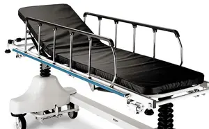
Stryker Stretcher 1231 Stretcher
Need answers fast?
Explore the manual using AI.
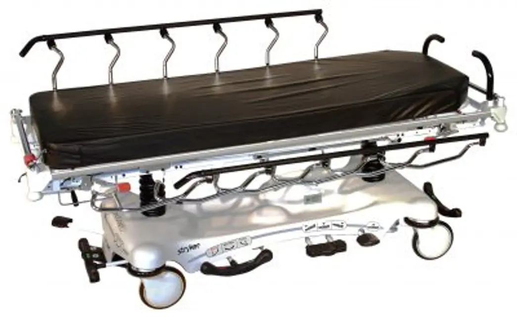
The Stryker Stretcher 1231 is a high-quality medical transport stretcher designed for optimal patient safety and comfort. This versatile stretcher features advanced hydraulic systems and durable construction, making it ideal for emergency medical services and hospital use. Regular maintenance ensures its reliability and longevity in critical care environments.
Turn manuals into instant answers
with your AI-powered assistantTurn manuals into instant answers
with your AI-powered assistant
Manual for Stryker Stretcher 1231 Stretcher
Complete asset maintenance, one click away
Get instant access to all the maintenance information you need. Empower technicians to perform preventive maintenance with asset packages, ready to use right out of the box.

Documents & Manuals
Find all the essential guides in one place.
 Tensioning Guide
- Belt-diagram
- C-120 pulleys
+ 13 more

Work Order Templates
Pre-built workflows to keep your asset running smoothly.
- Daily Electrical System Inspection
- Replace Roller and Pulley
- Install Engine B-120
+ 29 more

Procedures
Integrate maintenance plans directly into your work orders.
- Motion Industries
- Applied Industrial Technologies
- Electrical Brothers
+ 5 more

Parts
Access the parts list for your equipment in MaintainX.
- Drive Motor
- B2 Rollers
- Tensioning System
+ 40 more
Stryker Stretcher 1231 Stretcher
Create an account to install this asset package.
Maintenance Plans for Stryker Stretcher Model 1231 Stretcher
Integrate maintenance plans directly into your work orders in MaintainX.
Big Wheel Cam Gas Spring Dampener Replacement
Remove the litter top from the stretcher
Lift the base hood off the base frame
Remove the two clevis pins and rue ring cotters connecting the brake rods to the drive arm at the center of the base near the cam bracket assembly
Pull the brake shafts straight out away from the base
Remove the four hex washer head screws holding the cam bracket assembly to the base frame and remove the cam bracket assembly
Remove the rue ring cotter from the dampener mounting pin and remove the pin
Lift up on the (patient) left side of the cam bracket and remove the rue ring cotter holding the dampener to the dampener arm and remove the dampener
Reverse steps 1−7 to install the new dampener
Sign off on the dampener replacement

Big Wheel Carriage Assembly Replacement
Remove the litter top from the stretcher
Lift the base hood off the base frame
Remove the clevis pin and rue ring cotter connecting the brake rod to the brake rod drive link at each end of the stretcher
Remove the two clevis pins and rue ring cotters connecting the brake rods to the drive arm at the center of the base near the cam bracket assembly
Pull the brake shafts straight out away from the base
Remove the four hex washer head screws holding the cam bracket assembly to the base frame and remove the cam bracket assembly
Remove the two hex washer head screws holding the carriage weldment to the base frame and remove the carriage assembly
Reverse steps 1−7 to reinstall the carriage assembly
Sign off on the carriage assembly replacement
Big Wheel Replacement
Lift the base hood and separate the Velcro holding it to the base frame. Support the hood from the litter using bungee cords so it is out of the way.
Using a large, standard screwdriver, pop off the big wheel cover.
Using a small, standard screwdriver, remove the spiral retaining ring from the groove on the Big Wheel axle.
Remove the Big Wheel.
Reverse steps 1−4 to reinstall the Big Wheel.
Sign off on the Big Wheel replacement
Brake Ring Replacement
Pump the litter up to full height
Lift the base hood and support it from the litter using string or bungee cords
Unhook the extension springs from the top of the base caster tubes using needle−nose pliers
Remove the plastic caster covers
While putting pressure on the caster carriage bolt, use a 9/16” socket and a 3/8” drive ratchet to remove the caster nut on both sides of the stretcher
Remove the casters
Remove the brake rod
Remove the cotter pin from the clevis pin in the center of the brake ring weldment
Remove the cotter pin from the bearing pivot support
Brake Rod Replacement
Pump the litter up to full height.
Lift the base hood and support it from the litter using string or bungee cords.
Remove the hex head cap screws connecting the brake rod supports to the base frame.
Remove the bolt connecting the drive link assembly to the fifth wheel cam.
Remove the rue ring cotter and clevis pin connecting the rod end link to the side control link.
Remove the rue ring cotter connecting the drive link assembly to the bearing pivot support on the base frame (under the brake ring weldment).
Remove the three hex washer head screws holding the brake rod assembly to the base frame.
Remove the slotted spring pins connecting the butterfly “V” pedals, drive link assemblies and side control link to the brake rod.
Reverse steps 1−8 to reinstall the brake rod. When reinstalling the brake rod supports, torque the hex head cap screws to 12−15 ft.−lbs.
Parts for Stryker Stretcher 1231 Stretcher
Access the parts list for your equipment in MaintainX.
26" Fiberresin Foot Section Skin
0753-010-031
26" Steel Foot Section Skin
0753-010-033
29” Fiberresin Foot Section Skin
0753-010-032
29" Steel Foot Section Skin
0753-010-034
2nd Stage Assembly
1211-210-029
26" Fiberresin Foot Section Skin
0753-010-031
26" Steel Foot Section Skin
0753-010-033
29” Fiberresin Foot Section Skin
0753-010-032
29" Steel Foot Section Skin
0753-010-034
2nd Stage Assembly
1211-210-029
26" Fiberresin Foot Section Skin
0753-010-031
26" Steel Foot Section Skin
0753-010-033
29” Fiberresin Foot Section Skin
0753-010-032
29" Steel Foot Section Skin
0753-010-034
2nd Stage Assembly
1211-210-029
Unlock efficiency
with MaintainX CoPilot
MaintainX CoPilot is your expert colleague, on call 24/7, helping your team find the answers they need to keep equipment running.
'%20stroke-width='2.05034'/%3e%3cpath%20d='M43.601%2020.8897C43.2688%2019.252%2042.7312%2017.6627%2042.001%2016.1597'%20stroke='url(%23paint1_linear_4912_14668)'%20stroke-width='2.05034'/%3e%3cpath%20d='M40.001%2012.8882C38.8627%2011.3731%2037.516%2010.0265%2036.001%208.88818'%20stroke='url(%23paint2_linear_4912_14668)'%20stroke-width='2.05034'/%3e%3cpath%20d='M32.729%206.89053C31.2266%206.1604%2029.638%205.62282%2028.001%205.29053'%20stroke='url(%23paint3_linear_4912_14668)'%20stroke-width='2.05034'/%3e%3cpath%20d='M24.001%2014.8901V24.8901L32.001%2032.8901'%20stroke='url(%23paint4_linear_4912_14668)'%20stroke-width='2.05034'/%3e%3cdefs%3e%3clinearGradient%20id='paint0_linear_4912_14668'%20x1='4'%20y1='25'%20x2='44'%20y2='25'%20gradientUnits='userSpaceOnUse'%3e%3cstop%20stop-color='%23246CFF'/%3e%3cstop%20offset='1'%20stop-color='%232ED888'/%3e%3c/linearGradient%3e%3clinearGradient%20id='paint1_linear_4912_14668'%20x1='3.5'%20y1='20.8897'%20x2='44'%20y2='20.8897'%20gradientUnits='userSpaceOnUse'%3e%3cstop%20stop-color='%23246CFF'/%3e%3cstop%20offset='1'%20stop-color='%232ED888'/%3e%3c/linearGradient%3e%3clinearGradient%20id='paint2_linear_4912_14668'%20x1='3.5'%20y1='12.8882'%20x2='44.5'%20y2='12.8882'%20gradientUnits='userSpaceOnUse'%3e%3cstop%20stop-color='%23246CFF'/%3e%3cstop%20offset='1'%20stop-color='%232ED888'/%3e%3c/linearGradient%3e%3clinearGradient%20id='paint3_linear_4912_14668'%20x1='6.5'%20y1='6.89053'%20x2='43.5'%20y2='6.89053'%20gradientUnits='userSpaceOnUse'%3e%3cstop%20stop-color='%23246CFF'/%3e%3cstop%20offset='1'%20stop-color='%232ED888'/%3e%3c/linearGradient%3e%3clinearGradient%20id='paint4_linear_4912_14668'%20x1='5'%20y1='32.8901'%20x2='44'%20y2='32.8901'%20gradientUnits='userSpaceOnUse'%3e%3cstop%20stop-color='%23246CFF'/%3e%3cstop%20offset='1'%20stop-color='%232ED888'/%3e%3c/linearGradient%3e%3c/defs%3e%3c/svg%3e)
Reduce Unplanned Downtime
Ensure your team follows consistent procedures to minimize equipment failures and costly delays.
'%20stroke-width='2.05034'/%3e%3cpath%20d='M46.667%2041.7231C46.667%2044.5079%2045.5607%2047.1786%2043.5916%2049.1478C41.6225%2051.1169%2038.9518%2052.2231%2036.167%2052.2231C33.3822%2052.2231%2030.7115%2051.1169%2028.7424%2049.1478C26.7732%2047.1786%2025.667%2044.5079%2025.667%2041.7231C25.667%2038.9384%2026.7732%2036.2677%2028.7424%2034.2985C30.7115%2032.3294%2033.3822%2031.2231%2036.167%2031.2231C38.9518%2031.2231%2041.6225%2032.3294%2043.5916%2034.2985C45.5607%2036.2677%2046.667%2038.9384%2046.667%2041.7231Z'%20stroke='url(%23paint1_linear_4912_14680)'%20stroke-width='2.05034'/%3e%3cpath%20d='M37.334%2035.8896V40.5563H42.0007'%20stroke='url(%23paint2_linear_4912_14680)'%20stroke-width='2.05034'/%3e%3cdefs%3e%3clinearGradient%20id='paint0_linear_4912_14680'%20x1='5'%20y1='52.2231'%20x2='51'%20y2='52.2231'%20gradientUnits='userSpaceOnUse'%3e%3cstop%20stop-color='%23246CFF'/%3e%3cstop%20offset='1'%20stop-color='%232ED888'/%3e%3c/linearGradient%3e%3clinearGradient%20id='paint1_linear_4912_14680'%20x1='5'%20y1='52.2231'%20x2='47'%20y2='52.2231'%20gradientUnits='userSpaceOnUse'%3e%3cstop%20stop-color='%23246CFF'/%3e%3cstop%20offset='1'%20stop-color='%232ED888'/%3e%3c/linearGradient%3e%3clinearGradient%20id='paint2_linear_4912_14680'%20x1='5'%20y1='40.5563'%20x2='52.5'%20y2='40.5563'%20gradientUnits='userSpaceOnUse'%3e%3cstop%20stop-color='%23246CFF'/%3e%3cstop%20offset='1'%20stop-color='%232ED888'/%3e%3c/linearGradient%3e%3c/defs%3e%3c/svg%3e)
Maximize Asset Availability
Keep your assets running longer and more reliably, with standardized maintenance workflows from OEM manuals.
'%20stroke-width='2.05034'/%3e%3cpath%20d='M13.9995%2024.2231C13.9995%2029.1738%2015.9662%2033.9217%2019.4669%2037.4224C22.9675%2040.9231%2027.7155%2042.8897%2032.6662%2042.8897C37.6169%2042.8897%2042.3648%2040.9231%2045.8655%2037.4224C49.3662%2033.9217%2051.3328%2029.1738%2051.3328%2024.2231C51.3328%2019.2724%2049.3662%2014.5244%2045.8655%2011.0237C42.3648%207.52306%2037.6169%205.5564%2032.6662%205.5564C27.7155%205.5564%2022.9675%207.52306%2019.4669%2011.0237C15.9662%2014.5244%2013.9995%2019.2724%2013.9995%2024.2231Z'%20stroke='url(%23paint1_linear_4912_14674)'%20stroke-width='2.05034'/%3e%3cpath%20d='M32.6665%2017.2231V12.5564'%20stroke='url(%23paint2_linear_4912_14674)'%20stroke-width='2.05034'/%3e%3cpath%20d='M32.6665%2035.8898V31.2231'%20stroke='url(%23paint3_linear_4912_14674)'%20stroke-width='2.05034'/%3e%3cpath%20d='M37.9165%2020.7231V19.5565C37.9165%2018.9376%2037.6707%2018.3441%2037.2331%2017.9066C36.7955%2017.469%2036.202%2017.2231%2035.5832%2017.2231H29.7498C29.131%2017.2231%2028.5375%2017.469%2028.0999%2017.9066C27.6623%2018.3441%2027.4165%2018.9376%2027.4165%2019.5565V20.6018C27.4166%2021.1326%2027.5977%2021.6475%2027.9298%2022.0615C28.262%2022.4756%2028.7254%2022.764%2029.2435%2022.8791L36.0895%2024.4005C36.6077%2024.5157%2037.071%2024.8041%2037.4032%2025.2181C37.7353%2025.6321%2037.9164%2026.147%2037.9165%2026.6778V28.8898C37.9165%2029.5086%2037.6707%2030.1021%2037.2331%2030.5397C36.7955%2030.9773%2036.202%2031.2231%2035.5832%2031.2231H29.7498C29.131%2031.2231%2028.5375%2030.9773%2028.0999%2030.5397C27.6623%2030.1021%2027.4165%2029.5086%2027.4165%2028.8898V27.7231'%20stroke='url(%23paint4_linear_4912_14674)'%20stroke-width='2.05034'/%3e%3cdefs%3e%3clinearGradient%20id='paint0_linear_4912_14674'%20x1='5'%20y1='33.5'%20x2='50'%20y2='33.5'%20gradientUnits='userSpaceOnUse'%3e%3cstop%20stop-color='%23246CFF'/%3e%3cstop%20offset='1'%20stop-color='%232ED888'/%3e%3c/linearGradient%3e%3clinearGradient%20id='paint1_linear_4912_14674'%20x1='5'%20y1='42.8897'%20x2='48.5'%20y2='42.8897'%20gradientUnits='userSpaceOnUse'%3e%3cstop%20stop-color='%23246CFF'/%3e%3cstop%20offset='1'%20stop-color='%232ED888'/%3e%3c/linearGradient%3e%3clinearGradient%20id='paint2_linear_4912_14674'%20x1='5'%20y1='17.2231'%20x2='52.5'%20y2='17.2231'%20gradientUnits='userSpaceOnUse'%3e%3cstop%20stop-color='%23246CFF'/%3e%3cstop%20offset='1'%20stop-color='%232ED888'/%3e%3c/linearGradient%3e%3clinearGradient%20id='paint3_linear_4912_14674'%20x1='3.5'%20y1='35.8898'%20x2='50.5'%20y2='35.8898'%20gradientUnits='userSpaceOnUse'%3e%3cstop%20stop-color='%23246CFF'/%3e%3cstop%20offset='1'%20stop-color='%232ED888'/%3e%3c/linearGradient%3e%3clinearGradient%20id='paint4_linear_4912_14674'%20x1='3'%20y1='31.2231'%20x2='52'%20y2='31.2231'%20gradientUnits='userSpaceOnUse'%3e%3cstop%20stop-color='%23246CFF'/%3e%3cstop%20offset='1'%20stop-color='%232ED888'/%3e%3c/linearGradient%3e%3c/defs%3e%3c/svg%3e)
Lower Maintenance Costs
Turn any technician into an expert to streamline operations, maintain more assets, and reduce overall costs.
Thousands of companies manage their assets with MaintainX

'%3e%3cpath%20fill='url(%23b)'%20d='M66.008%2080.068c-5.084-.786-9.763-3.834-12.442-8.68a16.942%2016.942%200%200%201-1.87-5.18c1.096.19%202.203.476%203.298.87%206.525%202.333%2010.836%207.68%2011.014%2012.99ZM51.47%2061.576c.488-5.524%203.62-10.716%208.847-13.597a17.132%2017.132%200%200%201%2011.335-1.882c-.798%208.145-7.43%2014.848-16.038%2015.599-1.417.119-2.799.07-4.144-.12Zm28.564-11.478a17.513%2017.513%200%200%201%203.727%204.62c4.608%208.335%201.584%2018.813-6.75%2023.409a16.988%2016.988%200%200%201-4.359%201.679%2019.624%2019.624%200%200%201-3.977-12.776c.346-7.561%204.942-13.931%2011.36-16.932Z'/%3e%3cpath%20fill='%23110F0D'%20fill-rule='evenodd'%20d='M142.831%2048.324h4.977V77.03h-4.977V48.324Zm27.278%2013.002c.322%201.048.453%202.263.453%203.62v12.073h-4.787V66.208c0-.75-.047-1.572-.154-2.143-.453-2.382-1.822-3.572-4.215-3.572-2.31%200-3.882%201.274-4.43%203.476-.143.596-.226%201.405-.226%202.25v10.8h-4.787V56.623h4.477v2.989c1.536-2.5%203.906-3.43%206.371-3.43%203.488%200%206.263%201.68%207.298%205.144Zm24.636%207.323c0%203.882-2.358%206.525-5.763%207.727-1.298.453-2.632.643-4.62.643h-10.169V48.324h9.085c1.691%200%203.156.143%204.049.38%203.465.93%205.727%203.68%205.727%207.335%200%202.441-.81%204.156-2.762%205.644%202.905%201.417%204.453%203.727%204.453%206.966Zm-15.634-8.656h4.584c1.024%200%201.917-.143%202.536-.417%201.215-.548%201.905-1.608%201.905-3.167%200-1.548-.643-2.572-1.845-3.132-.691-.31-1.762-.452-2.763-.452h-4.417v7.168Zm10.716%208.465c0-1.536-.893-3.37-3.227-3.893-.428-.095-1.036-.143-1.571-.143h-5.918v8.085h5.501c.56%200%201.429-.048%201.953-.167%201.94-.453%203.262-1.846%203.262-3.882Zm47.747-11.847-8.097%2020.408h-4.429l-8.109-20.408h5.191l5.192%2014.574%205.108-14.574h5.144Zm-20.218%2010.002c0%20.69-.036%201.262-.155%201.94h-15.943c.631%202.87%202.714%204.728%205.882%204.728%202.131%200%203.607-.882%204.703-2.525h4.87c-1.762%204.144-5.204%206.692-9.657%206.692-6.084%200-10.537-4.858-10.537-10.49%200-6.108%204.524-10.776%2010.335-10.776%206.239%200%2010.442%204.954%2010.502%2010.43Zm-4.763-1.405c-.333-2.846-2.643-4.858-5.691-4.858-2.894%200-5.287%201.929-5.621%204.858h11.312Zm-72.667%203.44c0%204.787-3.287%208.371-9.419%208.371H119.363V64.66c-1.917.274-3.87.69-5.811%201.238l4.537%2011.121h-5.418l-3.596-9.585c-5.144%202.084-10.085%205.216-14.217%209.585h-4.786L101.8%2048.312h4.56l5.68%2013.883a44.112%2044.112%200%200%201%207.323-1.774V48.312h9.084c1.703%200%203.156.143%204.061.393%203.453.929%205.727%203.667%205.727%207.323%200%201.917-.738%204.179-2.81%205.691%203.06%201.56%204.501%204.025%204.501%206.93Zm-15.634-8.667a62.664%2062.664%200%200%201%202.06-.036c1.703.012%203.239.131%204.608.37%201.441-.549%202.357-1.727%202.357-3.537%200-1.941-.881-3.144-2.488-3.667-.548-.18-1.358-.286-2.322-.286h-4.215v7.156Zm-16.55%203.905-3.715-9.894-6.394%2016.502c2.833-2.595%206.263-4.858%2010.109-6.608Zm27.254%204.74c0-2.775-3.131-4.347-8.513-4.418-.715%200-1.441.011-2.191.047v8.252h5.918c2.548%200%204.786-1.37%204.786-3.882Z'%20clip-rule='evenodd'/%3e%3c/g%3e%3cdefs%3e%3clinearGradient%20id='b'%20x1='51.47'%20x2='85.916'%20y1='62.946'%20y2='62.946'%20gradientUnits='userSpaceOnUse'%3e%3cstop%20stop-color='%23CD9F28'/%3e%3cstop%20offset='1'%20stop-color='%23ECD80B'/%3e%3c/linearGradient%3e%3cclipPath%20id='a'%3e%3cpath%20fill='%23fff'%20d='M51.47%2045.728h186.104V80.14H51.47z'/%3e%3c/clipPath%3e%3c/defs%3e%3c/svg%3e)











More from Stryker



Explore Other Assets







© 2026 MaintainX. All rights reserved.