


'%3e%3cpath%20d='M10%2010.5V17h12.5v5.5l-21%20.038V15l8.5-4.5ZM1%206h11M6.5%202H12M5.5%2022.5V19'/%3e%3cpath%20d='M21.21%2017.012%2020.14%201.5h-4.28l-1.07%2015.512M15.516%206.49h4.967'/%3e%3c/g%3e%3cdefs%3e%3cclipPath%20id='a'%3e%3cpath%20fill='%23fff'%20d='M0%200h24v24H0z'/%3e%3c/clipPath%3e%3c/defs%3e%3c/svg%3e)











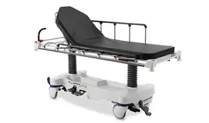
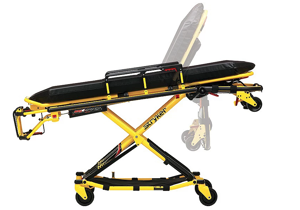
Stryker Stretcher 6092 EZ-Pro
Need answers fast?
Explore the manual using AI.
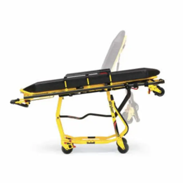
The Stryker Stretcher 6092 EZ-Pro is a high-quality, versatile medical transport solution designed for patient safety and comfort. This stretcher features advanced hydraulic systems and durable construction, making it ideal for emergency and hospital use. Ensure optimal performance with regular maintenance and quality spare parts.
Turn manuals into instant answers
with your AI-powered assistantTurn manuals into instant answers
with your AI-powered assistant
Manual for Stryker Stretcher 6092 EZ-Pro
Complete asset maintenance, one click away
Get instant access to all the maintenance information you need. Empower technicians to perform preventive maintenance with asset packages, ready to use right out of the box.

Documents & Manuals
Find all the essential guides in one place.
 Tensioning Guide
- Belt-diagram
- C-120 pulleys
+ 13 more

Work Order Templates
Pre-built workflows to keep your asset running smoothly.
- Daily Electrical System Inspection
- Replace Roller and Pulley
- Install Engine B-120
+ 29 more

Procedures
Integrate maintenance plans directly into your work orders.
- Motion Industries
- Applied Industrial Technologies
- Electrical Brothers
+ 5 more

Parts
Access the parts list for your equipment in MaintainX.
- Drive Motor
- B2 Rollers
- Tensioning System
+ 40 more
Stryker Stretcher 6092 EZ-Pro
Create an account to install this asset package.
Maintenance Plans for Stryker Stretcher Model 6092 EZ-Pro
Integrate maintenance plans directly into your work orders in MaintainX.
3-Stage I.V. Pole (Optional Equipment) Maintenance
Lift and pivot the pole from the storage position and push down until it is locked into receptacle (A)
Turn the lock actuator (B) counterclockwise and pull up on the bottom telescoping portion (C) of the pole to raise it to the desired height
Turn the lock actuator (B) clockwise to lock the bottom telescoping portion in place
For a higher I.V. pole, pull up on section (D) until the spring clip (E) engages
Hang I.V. bags on the I.V. hook (F)
To lower the I.V. pole, push in on the spring clip (E) and slide section (D) down into section (C). Turn the lock actuator (B) counterclockwise and slide section (C) into the bottom tube
Lift up and pivot the pole down into the storage position
Sign off on the I.V. pole maintenance

Auxiliary Lock Handle Adjustment
Bolt (A) removed
Auxiliary lock release link (B) pulled and held
Auxiliary lock lever (C) bottomed in the slot of the lever guard (D)
Direction of rod end (E) turn
Hole in the rod end (E) aligned with the weld nut in the auxiliary lock slide link (F)
Bolt (A) reinstalled
Sign off on the auxiliary lock handle adjustment
Checklist
All fasteners secure (reference all assembly prints)
All welds intact, not cracked or broken
No bent or broken tubing or sheet metal
No debris in wheels
All wheels secure, rolling and swivelling properly
Optional wheel lock holds wheel securely when on and clears wheel when off
Siderails move and latch properly
Backrest operating properly
Optional accessories intact and operating properly
Cot Height Replacement
Changing From the Loading to the Folded Position
Two operators stand at opposite ends of the cot and grasp the litter frame with palms facing up
The foot end operator unlocks the cot’s auxiliary lock
Both operators lift the cot until the weight is off the latching mechanism
The foot end operator squeezes and holds the release handle and both operators lower the cot to the folded position
Lowering the Cot from the Load Position to an Intermediate Transport Position
Two operators firmly grasp the litter frame at opposite ends with palms facing up
The foot end operator unlocks the auxiliary lock
Both operators lift the cot until the weight is off the latching mechanism
Foot End Release Handle Adjustment
Remove the bolt (G) and disconnect the link (B)
Lift the cot at both ends to take the weight off the base frame. Pull the foot end release handle and verify the patient left latch bar (C) is touching the foot end lever support bracket (E) at contact point 1
If the handle requires adjustment, remove the bolt (F), turn the rod end (H), and replace the bolt (F) until the conditions described in step 1 are achieved. Verify there is approximately 1/8” of clearance between the release handle and the grip on the lift bar
Replace bolt (G) to reconnect link (B)
Lift the cot at both ends to take the weight off the base frame. Pull the foot end release handle and verify the patient right latch bar (D) is touching the foot end lever support bracket (E) , at contact point 2. Verify the patient left latch bar (C) is touching the foot end lever support bracket (E) at contact point 1. Verify there is approximately 1/8” of clearance between the release handle and the grip on the lift bar
If the handle requires adjustment, remove the bolt (G),turn the rod end (H), and replace the bolt (G) until the conditions described in step 5 are achieved.
Sign off on the handle adjustment
Parts for Stryker Stretcher 6092 EZ-Pro
Access the parts list for your equipment in MaintainX.
Adhesive Loop Pile
6060-32-46
Clevis Pin
6082-31-31
Crutch Tip
830-10-35
Dome Hd. Rivet
25-79
Fiberlock Nut
16-28
Adhesive Loop Pile
6060-32-46
Clevis Pin
6082-31-31
Crutch Tip
830-10-35
Dome Hd. Rivet
25-79
Fiberlock Nut
16-28
Adhesive Loop Pile
6060-32-46
Clevis Pin
6082-31-31
Crutch Tip
830-10-35
Dome Hd. Rivet
25-79
Fiberlock Nut
16-28
Unlock
efficiency with MaintainX Assist
MaintainX Assist is your expert colleague, on call 24/7, helping your team find the answers they need to keep equipment running.
'/%3e%3cpath%20d='M32.0001%2048.6663C22.7953%2048.6663%2015.3335%2041.2043%2015.3335%2031.9997C15.3335%2022.7949%2022.7954%2015.333%2032.0001%2015.333C39.463%2015.333%2045.7096%2020.2378%2047.8335%2026.9997H43.6668'%20stroke='white'%20stroke-width='2.85714'%20stroke-linecap='round'%20stroke-linejoin='round'/%3e%3cpath%20d='M32%2025.333V31.9997L35.3333%2035.333'%20stroke='white'%20stroke-width='2.85714'%20stroke-linecap='round'%20stroke-linejoin='round'/%3e%3cpath%20d='M48.5918%2033.6667C48.6413%2033.1182%2048.6667%2032.5622%2048.6667%2032M37%2048.6667C37.5693%2048.4793%2038.1255%2048.2607%2038.6667%2048.013M46.651%2040.3333C46.9725%2039.714%2047.2592%2039.0722%2047.5083%2038.4103M42.3208%2045.7153C42.8948%2045.2402%2043.4385%2044.7263%2043.948%2044.1775'%20stroke='white'%20stroke-width='2.85714'%20stroke-linecap='round'%20stroke-linejoin='round'/%3e%3cdefs%3e%3clinearGradient%20id='paint0_linear_9036_2820'%20x1='17.4188'%20y1='24.2718'%20x2='46.9529'%20y2='57.2957'%20gradientUnits='userSpaceOnUse'%3e%3cstop%20stop-color='%23246CFF'/%3e%3cstop%20offset='1'%20stop-color='%2321C779'/%3e%3c/linearGradient%3e%3c/defs%3e%3c/svg%3e)
Reduce Unplanned Downtime
Ensure your team follows consistent procedures to minimize equipment failures and costly delays.
'/%3e%3cpath%20d='M15.7599%2038.0533C15.8165%2037.5147%2016.2068%2037.0805%2016.9875%2036.2123L18.706%2034.2912C19.126%2033.7593%2019.4241%2032.833%2019.4241%2031.9993C19.4241%2031.1663%2019.1259%2030.2397%2018.7059%2029.708L16.9875%2027.7869C16.2068%2026.9186%2015.8164%2026.4845%2015.7599%2025.9458C15.7033%2025.4071%2015.9949%2024.9011%2016.578%2023.889L17.4007%2022.4613C18.0228%2021.3816%2018.3339%2020.8417%2018.8632%2020.6265C19.3925%2020.4112%2019.9911%2020.5811%2021.1883%2020.9208L23.2221%2021.4936C23.9864%2021.6699%2024.7883%2021.5699%2025.4862%2021.2113L26.0477%2020.8874C26.6462%2020.504%2027.1065%2019.9389%2027.3613%2019.2746L27.9179%2017.6122C28.2839%2016.5122%2028.4668%2015.9622%2028.9024%2015.6476C29.3381%2015.333%2029.9167%2015.333%2031.0739%2015.333H32.9319C34.0892%2015.333%2034.6679%2015.333%2035.1034%2015.6476C35.5391%2015.9622%2035.7221%2016.5122%2036.0881%2017.6122L36.6446%2019.2746C36.8994%2019.9389%2037.3597%2020.504%2037.9582%2020.8874L38.5197%2021.2113C39.2176%2021.5699%2040.0196%2021.6699%2040.7839%2021.4936L42.8176%2020.9208C44.0147%2020.5811%2044.6134%2020.4112%2045.1427%2020.6265C45.6721%2020.8417%2045.9831%2021.3816%2046.6052%2022.4613L47.4279%2023.889C48.0111%2024.9011%2048.3026%2025.4071%2048.2461%2025.9458C48.1894%2026.4845%2047.7991%2026.9186%2047.0184%2027.7869L45.2999%2029.708C44.8801%2030.2397%2044.5817%2031.1663%2044.5817%2031.9993C44.5817%2032.833%2044.8799%2033.7593%2045.2999%2034.2912L47.0184%2036.2123C47.7991%2037.0805%2048.1894%2037.5147%2048.2461%2038.0533C48.3026%2038.5922%2048.0111%2039.0982%2047.4279%2040.1102L46.6052%2041.5378C45.9831%2042.6175%2045.6721%2043.1575%2045.1427%2043.3727C44.6134%2043.588%2044.0147%2043.4182%2042.8176%2043.0783L40.7839%2042.5055C40.0194%2042.3292%2039.2174%2042.4293%2038.5194%2042.788L37.9581%2043.112C37.3596%2043.4953%2036.8994%2044.0603%2036.6447%2044.7247L36.0881%2046.3872C35.7221%2047.4872%2035.5391%2048.0372%2035.1034%2048.3517C34.6679%2048.6663%2034.0892%2048.6663%2032.9319%2048.6663H31.0739C29.9167%2048.6663%2029.3381%2048.6663%2028.9024%2048.3517C28.4668%2048.0372%2028.2839%2047.4872%2027.9179%2046.3872'%20stroke='white'%20stroke-width='2.85714'%20stroke-linecap='round'/%3e%3cpath%20d='M16.5614%2043.2993C18.3614%2041.4993%2024.4814%2035.4393%2025.0814%2034.7393C25.7157%2033.9993%2025.2014%2032.9993%2025.5074%2029.8993C25.6555%2028.3993%2025.9781%2027.2756%2026.9014%2026.4393C28.0014%2025.3993%2028.9015%2025.3993%2032.0015%2025.3294C34.7015%2025.3993%2035.0215%2025.0993%2035.3015%2025.7994C35.5015%2026.2994%2034.9015%2026.5993%2034.1815%2027.3994C32.5815%2028.9993%2031.6415%2029.7993%2031.5515%2030.2993C30.9015%2032.4993%2033.4615%2033.7993%2034.8615%2032.3993C35.3908%2031.8698%2037.8415%2029.3993%2038.0815%2029.1993C38.2615%2029.0393%2038.6923%2029.047%2038.9015%2029.2993C39.0815%2029.4762%2039.1015%2029.4993%2039.0815%2030.2993C39.063%2031.0398%2039.0712%2032.103%2039.0735%2033.1993C39.0763%2034.6198%2039.0015%2036.1993%2038.4015%2036.9993C37.2015%2038.7993%2035.2015%2038.8993%2033.4015%2038.9793C31.7015%2039.0793%2030.3015%2038.8993%2029.8615%2039.2193C29.5015%2039.3993%2027.6014%2041.3993%2025.3014%2043.6993L21.2014%2047.7993C17.8014%2050.4993%2014.0614%2046.2993%2016.5614%2043.2993Z'%20stroke='white'%20stroke-width='2.85714'%20stroke-linecap='round'/%3e%3cdefs%3e%3clinearGradient%20id='paint0_linear_9036_2840'%20x1='17.4188'%20y1='24.2718'%20x2='46.9529'%20y2='57.2957'%20gradientUnits='userSpaceOnUse'%3e%3cstop%20stop-color='%23246CFF'/%3e%3cstop%20offset='1'%20stop-color='%2321C779'/%3e%3c/linearGradient%3e%3c/defs%3e%3c/svg%3e)
Maximize Asset Availability
Keep your assets running longer and more reliably, with standardized maintenance workflows from OEM manuals.
'/%3e%3cpath%20d='M35.3333%2041.9997C42.6972%2041.9997%2048.6667%2036.0302%2048.6667%2028.6663C48.6667%2021.3025%2042.6972%2015.333%2035.3333%2015.333C27.9695%2015.333%2022%2021.3025%2022%2028.6663C22%2036.0302%2027.9695%2041.9997%2035.3333%2041.9997Z'%20stroke='white'%20stroke-width='2.85714'%20stroke-linecap='round'/%3e%3cpath%20d='M17.2611%2030.333C16.0422%2032.1957%2015.3335%2034.4222%2015.3335%2036.8143C15.3335%2043.36%2020.6398%2048.6663%2027.1854%2048.6663C29.5777%2048.6663%2031.8042%2047.9577%2033.6668%2046.7387'%20stroke='white'%20stroke-width='2.85714'%20stroke-linecap='round'/%3e%3cpath%20d='M38.2854%2025.6752C37.9251%2024.155%2036.0911%2022.7832%2033.8896%2023.8095C31.6881%2024.8357%2031.3384%2028.1376%2034.6684%2028.4884C36.1736%2028.647%2037.1548%2028.3044%2038.0533%2029.2733C38.9516%2030.2422%2039.1186%2032.9365%2036.8219%2033.6627C34.5253%2034.3888%2032.2511%2033.2542%2032.0034%2031.6432M35.3104%2022.0068V23.4552M35.3104%2033.8862V35.3402'%20stroke='white'%20stroke-width='2.85714'%20stroke-linecap='round'%20stroke-linejoin='round'/%3e%3cdefs%3e%3clinearGradient%20id='paint0_linear_9036_2830'%20x1='17.4188'%20y1='24.2718'%20x2='46.9529'%20y2='57.2957'%20gradientUnits='userSpaceOnUse'%3e%3cstop%20stop-color='%23246CFF'/%3e%3cstop%20offset='1'%20stop-color='%2321C779'/%3e%3c/linearGradient%3e%3c/defs%3e%3c/svg%3e)
Lower Maintenance Costs
Turn any technician into an expert to streamline operations, maintain more assets, and reduce overall costs.
Thousands of companies manage their assets with MaintainX

'%3e%3cpath%20fill='url(%23b)'%20d='M66.008%2080.068c-5.084-.786-9.763-3.834-12.442-8.68a16.942%2016.942%200%200%201-1.87-5.18c1.096.19%202.203.476%203.298.87%206.525%202.333%2010.836%207.68%2011.014%2012.99ZM51.47%2061.576c.488-5.524%203.62-10.716%208.847-13.597a17.132%2017.132%200%200%201%2011.335-1.882c-.798%208.145-7.43%2014.848-16.038%2015.599-1.417.119-2.799.07-4.144-.12Zm28.564-11.478a17.513%2017.513%200%200%201%203.727%204.62c4.608%208.335%201.584%2018.813-6.75%2023.409a16.988%2016.988%200%200%201-4.359%201.679%2019.624%2019.624%200%200%201-3.977-12.776c.346-7.561%204.942-13.931%2011.36-16.932Z'/%3e%3cpath%20fill='%23110F0D'%20fill-rule='evenodd'%20d='M142.831%2048.324h4.977V77.03h-4.977V48.324Zm27.278%2013.002c.322%201.048.453%202.263.453%203.62v12.073h-4.787V66.208c0-.75-.047-1.572-.154-2.143-.453-2.382-1.822-3.572-4.215-3.572-2.31%200-3.882%201.274-4.43%203.476-.143.596-.226%201.405-.226%202.25v10.8h-4.787V56.623h4.477v2.989c1.536-2.5%203.906-3.43%206.371-3.43%203.488%200%206.263%201.68%207.298%205.144Zm24.636%207.323c0%203.882-2.358%206.525-5.763%207.727-1.298.453-2.632.643-4.62.643h-10.169V48.324h9.085c1.691%200%203.156.143%204.049.38%203.465.93%205.727%203.68%205.727%207.335%200%202.441-.81%204.156-2.762%205.644%202.905%201.417%204.453%203.727%204.453%206.966Zm-15.634-8.656h4.584c1.024%200%201.917-.143%202.536-.417%201.215-.548%201.905-1.608%201.905-3.167%200-1.548-.643-2.572-1.845-3.132-.691-.31-1.762-.452-2.763-.452h-4.417v7.168Zm10.716%208.465c0-1.536-.893-3.37-3.227-3.893-.428-.095-1.036-.143-1.571-.143h-5.918v8.085h5.501c.56%200%201.429-.048%201.953-.167%201.94-.453%203.262-1.846%203.262-3.882Zm47.747-11.847-8.097%2020.408h-4.429l-8.109-20.408h5.191l5.192%2014.574%205.108-14.574h5.144Zm-20.218%2010.002c0%20.69-.036%201.262-.155%201.94h-15.943c.631%202.87%202.714%204.728%205.882%204.728%202.131%200%203.607-.882%204.703-2.525h4.87c-1.762%204.144-5.204%206.692-9.657%206.692-6.084%200-10.537-4.858-10.537-10.49%200-6.108%204.524-10.776%2010.335-10.776%206.239%200%2010.442%204.954%2010.502%2010.43Zm-4.763-1.405c-.333-2.846-2.643-4.858-5.691-4.858-2.894%200-5.287%201.929-5.621%204.858h11.312Zm-72.667%203.44c0%204.787-3.287%208.371-9.419%208.371H119.363V64.66c-1.917.274-3.87.69-5.811%201.238l4.537%2011.121h-5.418l-3.596-9.585c-5.144%202.084-10.085%205.216-14.217%209.585h-4.786L101.8%2048.312h4.56l5.68%2013.883a44.112%2044.112%200%200%201%207.323-1.774V48.312h9.084c1.703%200%203.156.143%204.061.393%203.453.929%205.727%203.667%205.727%207.323%200%201.917-.738%204.179-2.81%205.691%203.06%201.56%204.501%204.025%204.501%206.93Zm-15.634-8.667a62.664%2062.664%200%200%201%202.06-.036c1.703.012%203.239.131%204.608.37%201.441-.549%202.357-1.727%202.357-3.537%200-1.941-.881-3.144-2.488-3.667-.548-.18-1.358-.286-2.322-.286h-4.215v7.156Zm-16.55%203.905-3.715-9.894-6.394%2016.502c2.833-2.595%206.263-4.858%2010.109-6.608Zm27.254%204.74c0-2.775-3.131-4.347-8.513-4.418-.715%200-1.441.011-2.191.047v8.252h5.918c2.548%200%204.786-1.37%204.786-3.882Z'%20clip-rule='evenodd'/%3e%3c/g%3e%3cdefs%3e%3clinearGradient%20id='b'%20x1='51.47'%20x2='85.916'%20y1='62.946'%20y2='62.946'%20gradientUnits='userSpaceOnUse'%3e%3cstop%20stop-color='%23CD9F28'/%3e%3cstop%20offset='1'%20stop-color='%23ECD80B'/%3e%3c/linearGradient%3e%3cclipPath%20id='a'%3e%3cpath%20fill='%23fff'%20d='M51.47%2045.728h186.104V80.14H51.47z'/%3e%3c/clipPath%3e%3c/defs%3e%3c/svg%3e)











More from Stryker




Explore Other Assets




© 2026 MaintainX. All rights reserved.