


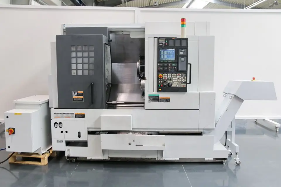
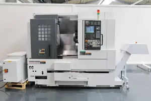
Mori Seiki CNC Turning Center NL2000S/500
Need answers fast?
Explore the manual using AI.
Turn manuals into instant answers
with your AI-powered assistantTurn manuals into instant answers
with your AI-powered assistant
Manual for Mori Seiki CNC Turning Center NL2000S/500
Complete asset maintenance, one click away
Get instant access to all the maintenance information you need. Empower technicians to perform preventive maintenance with asset packages, ready to use right out of the box.

Documents & Manuals
Find all the essential guides in one place.
 Tensioning Guide
- Belt-diagram
- C-120 pulleys
+ 13 more

Work Order Templates
Pre-built workflows to keep your asset running smoothly.
- Daily Electrical System Inspection
- Replace Roller and Pulley
- Install Engine B-120
+ 29 more

Procedures
Integrate maintenance plans directly into your work orders.
- Motion Industries
- Applied Industrial Technologies
- Electrical Brothers
+ 5 more

Parts
Access the parts list for your equipment in MaintainX.
- Drive Motor
- B2 Rollers
- Tensioning System
+ 40 more
Mori Seiki CNC Turning Center NL2000S/500
Create an account to install this asset package.
Maintenance Plans for Mori Seiki CNC Turning Center Model NL2000S/500
Integrate maintenance plans directly into your work orders in MaintainX.
High Pressure Coolant Unit Replenishing
19 HIGH PRESSURE COOLANT UNIT (OPTION)
WARNING
1. Do not operate the high pressure coolant unit or perform maintenance and inspections without reading and obtaining a thorough understanding of the contents of the operation manual provided with the high pressure coolant unit.
2. Keep the high pressure coolant unit operation manual on hand to enable immediate reference.
3. After the completion of the maintenance and inspections, remount all covers before running the machine.
19-3 Replenishing Coolant to Clean Tank
<Procedure>
1) Remove the separator cover.
WARNING

1000 Hourly V-Belt Inspection
19 HIGH PRESSURE COOLANT UNIT (OPTION)
WARNING
1. Do not operate the high pressure coolant unit or perform maintenance and inspections without reading and obtaining a thorough understanding of the contents of the operation manual provided with the high pressure coolant unit.
2. Keep the high pressure coolant unit operation manual on hand to enable immediate reference.
3. After the completion of the maintenance and inspections, remount all covers before running the machine.
19-5 High Pressure Pump Oil Replacement and V-Belt Inspection
<Procedure>
1) Remove the rear cover.
WARNING
1 Daily Spindle Warm-Up
CAUTION: Do not rotate the spindle without a workpiece clamped in the chuck.
Is a well-balanced workpiece, as small in diameter as possible, selected for the spindle warm-up?
Is the spindle warm-up performed below the maximum permissible rotation speed of the chuck, workpiece, and fixture?
Are the chuck, workpiece, fixture, and tool mounted securely before performing the spindle warm-up?
Is the rotary tool-spindle warm-up performed at or below the maximum permissible rotation speed of tool holder?
Is the tool to be mounted on the rotary tool-spindle a small diameter tool that can be rotated at the maximum spindle speed or more?
NOTE: Adjust the rotation speed for warm-up based on the maximum rotation speed for the machining programs used for the day.
Enter the rotation speed for warm-up
Sign off on the daily spindle warm-up
1 Yearly Batteries Replacement
17 ELECTRICAL CABINET
17-4 Replacing Batteries
CAUTION
1. Change the NC memory back-up battery and servo absolute position sensing battery with power supplied to the NC.
2. Before changing the batteries, save the memory data such as parameters and programs as backup in an external I/O device.
3. Always ensure that the polarity of the batteries is correct.
<Procedure>
Function selection key (SYSTEM) → [PERIODIC INSPECT.]
Confirm 'BATTERY REPLACEMENT' accumulate time.
1 Daily Chip Conveyor Cleaning
Warning: Disconnect power before placing rags on the conveyor belt to avoid serious injury.
Press the chip conveyor button [FOR] (Forward). The indicator should be illuminated. The chip conveyor should move forward to discharge chips from machine.
Press the chip conveyor button [STOP] (Stop). The indicator should be illuminated. The chip conveyor should stop.
Place an adequate quantity of rags on the conveyor belt.
Press the chip conveyor button [FOR] (Forward). The indicator should be illuminated.
Keep pressing the chip conveyor button [FOR] (Forward). The chip conveyor should move forward to discharge chips and rags out of the machine only when the button is pressed.
Note: Steps 4) and 5) are for the scraper type chip conveyor. For the hinge type chip conveyor, move the chip conveyor backward by pressing the chip conveyor button [BACK] (Reverse).
For further details on the cleaning procedure, refer to the chip conveyor instruction manual published separately.
Sign off on the chip conveyor cleaning
Parts for Mori Seiki CNC Turning Center NL2000S/500
Access the parts list for your equipment in MaintainX.
Oil Tank 10 L
U00535A
Manifold BT-202-50-S
U00536A
Manifold BT-102-50-S, UK4273-1
U00532A
Manifold BT-202-50-S, UK4276-1
U00530B
Pipe
R82687A
Oil Tank 10 L
U00535A
Manifold BT-202-50-S
U00536A
Manifold BT-102-50-S, UK4273-1
U00532A
Manifold BT-202-50-S, UK4276-1
U00530B
Pipe
R82687A
Oil Tank 10 L
U00535A
Manifold BT-202-50-S
U00536A
Manifold BT-102-50-S, UK4273-1
U00532A
Manifold BT-202-50-S, UK4276-1
U00530B
Pipe
R82687A
Unlock efficiency
with MaintainX CoPilot
MaintainX CoPilot is your expert colleague, on call 24/7, helping your team find the answers they need to keep equipment running.
Reduce Unplanned Downtime
Ensure your team follows consistent procedures to minimize equipment failures and costly delays.
Maximize Asset Availability
Keep your assets running longer and more reliably, with standardized maintenance workflows from OEM manuals.
Lower Maintenance Costs
Turn any technician into an expert to streamline operations, maintain more assets, and reduce overall costs.
Thousands of companies manage their assets with MaintainX

'%3e%3cpath%20fill='url(%23b)'%20d='M66.008%2080.068c-5.084-.786-9.763-3.834-12.442-8.68a16.942%2016.942%200%200%201-1.87-5.18c1.096.19%202.203.476%203.298.87%206.525%202.333%2010.836%207.68%2011.014%2012.99ZM51.47%2061.576c.488-5.524%203.62-10.716%208.847-13.597a17.132%2017.132%200%200%201%2011.335-1.882c-.798%208.145-7.43%2014.848-16.038%2015.599-1.417.119-2.799.07-4.144-.12Zm28.564-11.478a17.513%2017.513%200%200%201%203.727%204.62c4.608%208.335%201.584%2018.813-6.75%2023.409a16.988%2016.988%200%200%201-4.359%201.679%2019.624%2019.624%200%200%201-3.977-12.776c.346-7.561%204.942-13.931%2011.36-16.932Z'/%3e%3cpath%20fill='%23110F0D'%20fill-rule='evenodd'%20d='M142.831%2048.324h4.977V77.03h-4.977V48.324Zm27.278%2013.002c.322%201.048.453%202.263.453%203.62v12.073h-4.787V66.208c0-.75-.047-1.572-.154-2.143-.453-2.382-1.822-3.572-4.215-3.572-2.31%200-3.882%201.274-4.43%203.476-.143.596-.226%201.405-.226%202.25v10.8h-4.787V56.623h4.477v2.989c1.536-2.5%203.906-3.43%206.371-3.43%203.488%200%206.263%201.68%207.298%205.144Zm24.636%207.323c0%203.882-2.358%206.525-5.763%207.727-1.298.453-2.632.643-4.62.643h-10.169V48.324h9.085c1.691%200%203.156.143%204.049.38%203.465.93%205.727%203.68%205.727%207.335%200%202.441-.81%204.156-2.762%205.644%202.905%201.417%204.453%203.727%204.453%206.966Zm-15.634-8.656h4.584c1.024%200%201.917-.143%202.536-.417%201.215-.548%201.905-1.608%201.905-3.167%200-1.548-.643-2.572-1.845-3.132-.691-.31-1.762-.452-2.763-.452h-4.417v7.168Zm10.716%208.465c0-1.536-.893-3.37-3.227-3.893-.428-.095-1.036-.143-1.571-.143h-5.918v8.085h5.501c.56%200%201.429-.048%201.953-.167%201.94-.453%203.262-1.846%203.262-3.882Zm47.747-11.847-8.097%2020.408h-4.429l-8.109-20.408h5.191l5.192%2014.574%205.108-14.574h5.144Zm-20.218%2010.002c0%20.69-.036%201.262-.155%201.94h-15.943c.631%202.87%202.714%204.728%205.882%204.728%202.131%200%203.607-.882%204.703-2.525h4.87c-1.762%204.144-5.204%206.692-9.657%206.692-6.084%200-10.537-4.858-10.537-10.49%200-6.108%204.524-10.776%2010.335-10.776%206.239%200%2010.442%204.954%2010.502%2010.43Zm-4.763-1.405c-.333-2.846-2.643-4.858-5.691-4.858-2.894%200-5.287%201.929-5.621%204.858h11.312Zm-72.667%203.44c0%204.787-3.287%208.371-9.419%208.371H119.363V64.66c-1.917.274-3.87.69-5.811%201.238l4.537%2011.121h-5.418l-3.596-9.585c-5.144%202.084-10.085%205.216-14.217%209.585h-4.786L101.8%2048.312h4.56l5.68%2013.883a44.112%2044.112%200%200%201%207.323-1.774V48.312h9.084c1.703%200%203.156.143%204.061.393%203.453.929%205.727%203.667%205.727%207.323%200%201.917-.738%204.179-2.81%205.691%203.06%201.56%204.501%204.025%204.501%206.93Zm-15.634-8.667a62.664%2062.664%200%200%201%202.06-.036c1.703.012%203.239.131%204.608.37%201.441-.549%202.357-1.727%202.357-3.537%200-1.941-.881-3.144-2.488-3.667-.548-.18-1.358-.286-2.322-.286h-4.215v7.156Zm-16.55%203.905-3.715-9.894-6.394%2016.502c2.833-2.595%206.263-4.858%2010.109-6.608Zm27.254%204.74c0-2.775-3.131-4.347-8.513-4.418-.715%200-1.441.011-2.191.047v8.252h5.918c2.548%200%204.786-1.37%204.786-3.882Z'%20clip-rule='evenodd'/%3e%3c/g%3e%3cdefs%3e%3clinearGradient%20id='b'%20x1='51.47'%20x2='85.916'%20y1='62.946'%20y2='62.946'%20gradientUnits='userSpaceOnUse'%3e%3cstop%20stop-color='%23CD9F28'/%3e%3cstop%20offset='1'%20stop-color='%23ECD80B'/%3e%3c/linearGradient%3e%3cclipPath%20id='a'%3e%3cpath%20fill='%23fff'%20d='M51.47%2045.728h186.104V80.14H51.47z'/%3e%3c/clipPath%3e%3c/defs%3e%3c/svg%3e)


More from Mori Seiki


Explore Other Assets


© 2026 MaintainX. All rights reserved.