


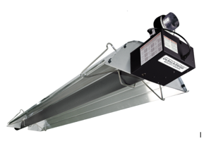
Roberts-Gordon Infrared Heater BH-175
Need answers fast?
Explore the manual using AI.

Turn manuals into instant answers
with your AI-powered assistantTurn manuals into instant answers
with your AI-powered assistant
Manual for Roberts-Gordon Infrared Heater BH-175
Complete asset maintenance, one click away
Get instant access to all the maintenance information you need. Empower technicians to perform preventive maintenance with asset packages, ready to use right out of the box.

Documents & Manuals
Find all the essential guides in one place.
 Tensioning Guide
- Belt-diagram
- C-120 pulleys
+ 13 more

Work Order Templates
Pre-built workflows to keep your asset running smoothly.
- Daily Electrical System Inspection
- Replace Roller and Pulley
- Install Engine B-120
+ 29 more

Procedures
Integrate maintenance plans directly into your work orders.
- Motion Industries
- Applied Industrial Technologies
- Electrical Brothers
+ 5 more

Parts
Access the parts list for your equipment in MaintainX.
- Drive Motor
- B2 Rollers
- Tensioning System
+ 40 more
Roberts-Gordon Infrared Heater BH-175
Create an account to install this asset package.
Maintenance Plans for Roberts-Gordon Infrared Heater Model BH-175
Integrate maintenance plans directly into your work orders in MaintainX.
1 Yearly Heater Vicinity Inspection
The Vicinity of the Heater
Do not store or use flammable objects, liquids, or vapors near the heater
Immediately remove these items if they are present
Vehicles and Other Objects
Maintain the clearances to combustibles
Do not hang anything from, or place anything on, the heater
Make sure nothing is lodged underneath the reflector, in between the tubes, or in the decorative or protective grilles included with select models
Immediately remove objects in violation of the clearances to combustibles
See Page 5, Section 3

1 Yearly Wall Tag Inspection
Wall tag present
Wall tag legible and accurate
If wall tag is not present or not accurate, contact Roberts-Gordon LLC or your ROBERTS GORDON independent distributor
Affix the tag by peeling off the backing of the adhesive strips on the rear surface and position the tag on a wall near the heater (e.g. thermostat or ROBERTS GORDON® Controller)
Upload a photo of the affixed wall tag
Enter your model number and installed configuration
Write the proper clearance dimensions in permanent ink according to your model number and configuration in the open spaces on the tag
Sign off on the wall tag inspection
1 Yearly Reflector Inspection
Reflector.; Support reflector with reflector hanger and support strap.; Reflector must not touch tube.; Make sure there is no dirt, sagging, cracking, or distortion.; Do not operate if there is sagging, cracking, or distortion.; Make sure reflectors are correctly overlapped.; See Page 25, Section 6.5.1.; Clean outside surface with a damp cloth.; Step 6.5.1 Reflector, U-Clip and Reflector Support Installation
The pictorial drawings of the heater construction in Section 6 are schematic only and provide a general guideline of where hangers, reflector supports and U-clips are to be installed
To ensure proper expansion and contraction movement of the reflectors, a combination of U-clips and reflector supports are used
The positioning of reflector supports and U-clips depend on the individual installation
Use either pop rivets or sheet metal screws instead of u-clips when installing end caps and joint pieces in areas where impact and high wind may be a factor
The following rules must be observed
Slide first reflector after burner a minimum 2” (4 cm) through first hanger and ensure reflector end cap is securely fastened via U-clips, pop rivets, or sheet metal screws
Position reflector support with tight screws in middle of first reflector
The overlap at the first and second reflector is a slip overlap
1 Yearly Thermostat Inspection
SECTION 10: WIRING DANGER - Electrical Shock Hazard - Disconnect electric before service - Heater must be properly earthed - Failure to follow these instructions can result in death or electrical shock
No exposed wire or damage to the thermostat
Heaters can be controlled using several methods. Normally thermostats are used to control the heaters but they can also be controlled by an energy management system.
Choose the connection for heaters
Heaters must be grounded in accordance with applicable codes: United States: Refer to National Electrical Code® NFPA 70 - latest revision Canada: Refer to Canadian Electrical Code CSA C22.1 Part I - latest revision
If any of the original internal wiring must be replaced, it must be replaced with wiring materials having a temperature rating of at least 105 °C and 600 volts
Sign off on the thermostat inspection
1 Yearly Gas Piping Inspection
SECTION 9: GAS PIPING
WARNING: Fire Hazard
Gas hose fittings tightened according to Figure 23
Gas hose not cracked or twisted
Gas hose moves during normal operation
36\ (91 cm) long connector of 1/2\" or 3/4\" nominal ID used"
WARNING: Explosion Hazard
Gas hose installed as shown on Page 46, Figure 24
High pressure testing of the gas piping completed
Parts for Roberts-Gordon Infrared Heater BH-175
Access the parts list for your equipment in MaintainX.
Burner (Rate And Fuel Varies)
071XXXXX
Blower Assembly With Cord
90709700
Gasket (Burner To Burner Tube)
2568200
Gasket (Blower To Burner)
90709801
Installation, Operation And Service Manual
170101NA
Burner (Rate And Fuel Varies)
071XXXXX
Blower Assembly With Cord
90709700
Gasket (Burner To Burner Tube)
2568200
Gasket (Blower To Burner)
90709801
Installation, Operation And Service Manual
170101NA
Burner (Rate And Fuel Varies)
071XXXXX
Blower Assembly With Cord
90709700
Gasket (Burner To Burner Tube)
2568200
Gasket (Blower To Burner)
90709801
Installation, Operation And Service Manual
170101NA
Unlock efficiency
with MaintainX CoPilot
MaintainX CoPilot is your expert colleague, on call 24/7, helping your team find the answers they need to keep equipment running.
Reduce Unplanned Downtime
Ensure your team follows consistent procedures to minimize equipment failures and costly delays.
Maximize Asset Availability
Keep your assets running longer and more reliably, with standardized maintenance workflows from OEM manuals.
Lower Maintenance Costs
Turn any technician into an expert to streamline operations, maintain more assets, and reduce overall costs.
Thousands of companies manage their assets with MaintainX

'%3e%3cpath%20fill='url(%23b)'%20d='M66.008%2080.068c-5.084-.786-9.763-3.834-12.442-8.68a16.942%2016.942%200%200%201-1.87-5.18c1.096.19%202.203.476%203.298.87%206.525%202.333%2010.836%207.68%2011.014%2012.99ZM51.47%2061.576c.488-5.524%203.62-10.716%208.847-13.597a17.132%2017.132%200%200%201%2011.335-1.882c-.798%208.145-7.43%2014.848-16.038%2015.599-1.417.119-2.799.07-4.144-.12Zm28.564-11.478a17.513%2017.513%200%200%201%203.727%204.62c4.608%208.335%201.584%2018.813-6.75%2023.409a16.988%2016.988%200%200%201-4.359%201.679%2019.624%2019.624%200%200%201-3.977-12.776c.346-7.561%204.942-13.931%2011.36-16.932Z'/%3e%3cpath%20fill='%23110F0D'%20fill-rule='evenodd'%20d='M142.831%2048.324h4.977V77.03h-4.977V48.324Zm27.278%2013.002c.322%201.048.453%202.263.453%203.62v12.073h-4.787V66.208c0-.75-.047-1.572-.154-2.143-.453-2.382-1.822-3.572-4.215-3.572-2.31%200-3.882%201.274-4.43%203.476-.143.596-.226%201.405-.226%202.25v10.8h-4.787V56.623h4.477v2.989c1.536-2.5%203.906-3.43%206.371-3.43%203.488%200%206.263%201.68%207.298%205.144Zm24.636%207.323c0%203.882-2.358%206.525-5.763%207.727-1.298.453-2.632.643-4.62.643h-10.169V48.324h9.085c1.691%200%203.156.143%204.049.38%203.465.93%205.727%203.68%205.727%207.335%200%202.441-.81%204.156-2.762%205.644%202.905%201.417%204.453%203.727%204.453%206.966Zm-15.634-8.656h4.584c1.024%200%201.917-.143%202.536-.417%201.215-.548%201.905-1.608%201.905-3.167%200-1.548-.643-2.572-1.845-3.132-.691-.31-1.762-.452-2.763-.452h-4.417v7.168Zm10.716%208.465c0-1.536-.893-3.37-3.227-3.893-.428-.095-1.036-.143-1.571-.143h-5.918v8.085h5.501c.56%200%201.429-.048%201.953-.167%201.94-.453%203.262-1.846%203.262-3.882Zm47.747-11.847-8.097%2020.408h-4.429l-8.109-20.408h5.191l5.192%2014.574%205.108-14.574h5.144Zm-20.218%2010.002c0%20.69-.036%201.262-.155%201.94h-15.943c.631%202.87%202.714%204.728%205.882%204.728%202.131%200%203.607-.882%204.703-2.525h4.87c-1.762%204.144-5.204%206.692-9.657%206.692-6.084%200-10.537-4.858-10.537-10.49%200-6.108%204.524-10.776%2010.335-10.776%206.239%200%2010.442%204.954%2010.502%2010.43Zm-4.763-1.405c-.333-2.846-2.643-4.858-5.691-4.858-2.894%200-5.287%201.929-5.621%204.858h11.312Zm-72.667%203.44c0%204.787-3.287%208.371-9.419%208.371H119.363V64.66c-1.917.274-3.87.69-5.811%201.238l4.537%2011.121h-5.418l-3.596-9.585c-5.144%202.084-10.085%205.216-14.217%209.585h-4.786L101.8%2048.312h4.56l5.68%2013.883a44.112%2044.112%200%200%201%207.323-1.774V48.312h9.084c1.703%200%203.156.143%204.061.393%203.453.929%205.727%203.667%205.727%207.323%200%201.917-.738%204.179-2.81%205.691%203.06%201.56%204.501%204.025%204.501%206.93Zm-15.634-8.667a62.664%2062.664%200%200%201%202.06-.036c1.703.012%203.239.131%204.608.37%201.441-.549%202.357-1.727%202.357-3.537%200-1.941-.881-3.144-2.488-3.667-.548-.18-1.358-.286-2.322-.286h-4.215v7.156Zm-16.55%203.905-3.715-9.894-6.394%2016.502c2.833-2.595%206.263-4.858%2010.109-6.608Zm27.254%204.74c0-2.775-3.131-4.347-8.513-4.418-.715%200-1.441.011-2.191.047v8.252h5.918c2.548%200%204.786-1.37%204.786-3.882Z'%20clip-rule='evenodd'/%3e%3c/g%3e%3cdefs%3e%3clinearGradient%20id='b'%20x1='51.47'%20x2='85.916'%20y1='62.946'%20y2='62.946'%20gradientUnits='userSpaceOnUse'%3e%3cstop%20stop-color='%23CD9F28'/%3e%3cstop%20offset='1'%20stop-color='%23ECD80B'/%3e%3c/linearGradient%3e%3cclipPath%20id='a'%3e%3cpath%20fill='%23fff'%20d='M51.47%2045.728h186.104V80.14H51.47z'/%3e%3c/clipPath%3e%3c/defs%3e%3c/svg%3e)


More from Roberts-Gordon


Explore Other Assets


© 2026 MaintainX. All rights reserved.