


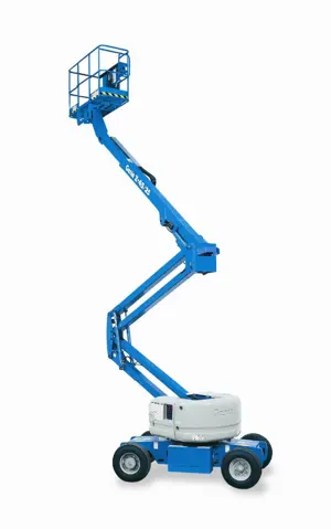
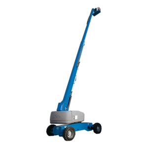
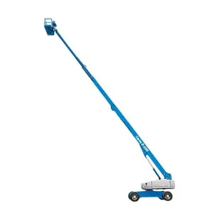
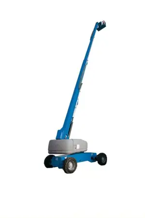
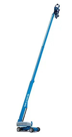
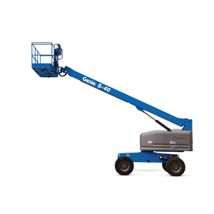
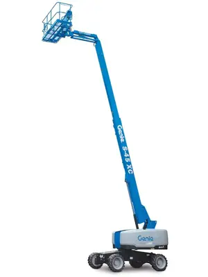
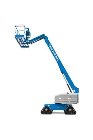
Genie Articulated Boom Lift Z-30N
Need answers fast?
Explore the manual using AI.

The Genie Articulated Boom Lift Z-30N is a versatile aerial work platform designed for efficient access in tight spaces. Known for its reliability and maneuverability, this model is ideal for construction and maintenance tasks, ensuring safety and productivity at height. Trust Genie for your lifting solutions.
Turn manuals into instant answers
with your AI-powered assistantTurn manuals into instant answers
with your AI-powered assistant
Manual for Genie Articulated Boom Lift Z-30N
Complete asset maintenance, one click away
Get instant access to all the maintenance information you need. Empower technicians to perform preventive maintenance with asset packages, ready to use right out of the box.

Documents & Manuals
Find all the essential guides in one place.
 Tensioning Guide
- Belt-diagram
- C-120 pulleys
+ 13 more

Work Order Templates
Pre-built workflows to keep your asset running smoothly.
- Daily Electrical System Inspection
- Replace Roller and Pulley
- Install Engine B-120
+ 29 more

Procedures
Integrate maintenance plans directly into your work orders.
- Motion Industries
- Applied Industrial Technologies
- Electrical Brothers
+ 5 more

Parts
Access the parts list for your equipment in MaintainX.
- Drive Motor
- B2 Rollers
- Tensioning System
+ 40 more
Genie Articulated Boom Lift Z-30N
Create an account to install this asset package.
Maintenance Plans for Genie Articulated Boom Lift Model Z-30N
Integrate maintenance plans directly into your work orders in MaintainX.
4000 Hourly Engine Maintenance
- Perform Engine Maintenance
Required maintenance procedures and additional engine information are available in the manufacturer's manuals. Refer to Specifications, Engine Operator and Maintenance Manuals
Perkins Models, every 4000 hours (p.171):
854F-34T, 1104D-44T:
• Aftercooler core - clean/test
GM 3.0L, every 5000 hours (p.172):
• Cooling system coolant - replace
Perkins 1104D-44T, every 6000 hours, (p.172)
• Cooling system coolant extender (ELC) - add

3 Monthly Operator Protection Alarm Test
Warning: This test requires trained personnel!
Is the key switch turned to platform control?
Is the red Emergency Stop button in the on position at both the ground and platform controls?
Engine started from the platform controls (for engine powered models)?
No audible alarm or flashing beacon when operator protection activation strip is pressed without activating the foot switch?
Intermittent audible alarm sounds and the beacon flashes when operator protection activation bar is pressed for longer than 0.4 seconds and released with foot switch activated?
Continuous audible alarm sounds after 10 seconds?
Audible alarm and flashing beacon turn off after pressing the reset button?
Sign off on the Operator Protection Alarm Test
3 Monthly Aircraft Protection System Test
Start this procedure with the machine in the fully stowed position
Turn the key switch to platform control and pull out the red Emergency Stop button to the on position at both the ground and platform controls
Start the engine from the platform controls
Move the yellow bumper at the bottom of the platform 4 inches/10 cm in any direction
Activate each function control handle or toggle switch
Extend the primary boom approximately 3 ft / 1 m
Move the yellow bumper at the bottom of the platform 4 inches/10 cm in any direction
Activate each function control handle or toggle switch
Activate and hold the aircraft protection override switch
3 Monthly Electrical Wiring Inspection
- Inspect the Electrical Wiring
WARNING!
Electrocution/burn hazard
Contact with electrically charged circuits could result in death or serious injury. Remove all rings, watches and other jewelry
1. Inspect the following areas for burnt, chafed, corroded pinched and loose wires:
Note: Inspection areas will vary by model
• Engine wiring harness
• Engine relay block
• Hydraulic manifold wiring
Initial 50 Hours Engine Maintenance
Ford Models:
- Oil, coolant, fuel, exhaust and vacuum
hoses - check for leaks, damage or deterioration
- Electrical wiring - check for chafing or damage
Kubota Models:
- Engine oil - replace
- Oil filter - replace
GM .998L:
- Cylinder head bolts - torque (40.5 ft-lbs / 55 Nm)
Parts for Genie Articulated Boom Lift Z-30N
Access the parts list for your equipment in MaintainX.
Digital Level Kit
58351
Digital Protractor
58377
O-ring Field Service Kit
49612
Digital Level Kit
58351
Digital Protractor
58377
O-ring Field Service Kit
49612
Digital Level Kit
58351
Digital Protractor
58377
O-ring Field Service Kit
49612
Unlock efficiency
with MaintainX CoPilot
MaintainX CoPilot is your expert colleague, on call 24/7, helping your team find the answers they need to keep equipment running.
Reduce Unplanned Downtime
Ensure your team follows consistent procedures to minimize equipment failures and costly delays.
Maximize Asset Availability
Keep your assets running longer and more reliably, with standardized maintenance workflows from OEM manuals.
Lower Maintenance Costs
Turn any technician into an expert to streamline operations, maintain more assets, and reduce overall costs.
Thousands of companies manage their assets with MaintainX

'%3e%3cpath%20fill='url(%23b)'%20d='M66.008%2080.068c-5.084-.786-9.763-3.834-12.442-8.68a16.942%2016.942%200%200%201-1.87-5.18c1.096.19%202.203.476%203.298.87%206.525%202.333%2010.836%207.68%2011.014%2012.99ZM51.47%2061.576c.488-5.524%203.62-10.716%208.847-13.597a17.132%2017.132%200%200%201%2011.335-1.882c-.798%208.145-7.43%2014.848-16.038%2015.599-1.417.119-2.799.07-4.144-.12Zm28.564-11.478a17.513%2017.513%200%200%201%203.727%204.62c4.608%208.335%201.584%2018.813-6.75%2023.409a16.988%2016.988%200%200%201-4.359%201.679%2019.624%2019.624%200%200%201-3.977-12.776c.346-7.561%204.942-13.931%2011.36-16.932Z'/%3e%3cpath%20fill='%23110F0D'%20fill-rule='evenodd'%20d='M142.831%2048.324h4.977V77.03h-4.977V48.324Zm27.278%2013.002c.322%201.048.453%202.263.453%203.62v12.073h-4.787V66.208c0-.75-.047-1.572-.154-2.143-.453-2.382-1.822-3.572-4.215-3.572-2.31%200-3.882%201.274-4.43%203.476-.143.596-.226%201.405-.226%202.25v10.8h-4.787V56.623h4.477v2.989c1.536-2.5%203.906-3.43%206.371-3.43%203.488%200%206.263%201.68%207.298%205.144Zm24.636%207.323c0%203.882-2.358%206.525-5.763%207.727-1.298.453-2.632.643-4.62.643h-10.169V48.324h9.085c1.691%200%203.156.143%204.049.38%203.465.93%205.727%203.68%205.727%207.335%200%202.441-.81%204.156-2.762%205.644%202.905%201.417%204.453%203.727%204.453%206.966Zm-15.634-8.656h4.584c1.024%200%201.917-.143%202.536-.417%201.215-.548%201.905-1.608%201.905-3.167%200-1.548-.643-2.572-1.845-3.132-.691-.31-1.762-.452-2.763-.452h-4.417v7.168Zm10.716%208.465c0-1.536-.893-3.37-3.227-3.893-.428-.095-1.036-.143-1.571-.143h-5.918v8.085h5.501c.56%200%201.429-.048%201.953-.167%201.94-.453%203.262-1.846%203.262-3.882Zm47.747-11.847-8.097%2020.408h-4.429l-8.109-20.408h5.191l5.192%2014.574%205.108-14.574h5.144Zm-20.218%2010.002c0%20.69-.036%201.262-.155%201.94h-15.943c.631%202.87%202.714%204.728%205.882%204.728%202.131%200%203.607-.882%204.703-2.525h4.87c-1.762%204.144-5.204%206.692-9.657%206.692-6.084%200-10.537-4.858-10.537-10.49%200-6.108%204.524-10.776%2010.335-10.776%206.239%200%2010.442%204.954%2010.502%2010.43Zm-4.763-1.405c-.333-2.846-2.643-4.858-5.691-4.858-2.894%200-5.287%201.929-5.621%204.858h11.312Zm-72.667%203.44c0%204.787-3.287%208.371-9.419%208.371H119.363V64.66c-1.917.274-3.87.69-5.811%201.238l4.537%2011.121h-5.418l-3.596-9.585c-5.144%202.084-10.085%205.216-14.217%209.585h-4.786L101.8%2048.312h4.56l5.68%2013.883a44.112%2044.112%200%200%201%207.323-1.774V48.312h9.084c1.703%200%203.156.143%204.061.393%203.453.929%205.727%203.667%205.727%207.323%200%201.917-.738%204.179-2.81%205.691%203.06%201.56%204.501%204.025%204.501%206.93Zm-15.634-8.667a62.664%2062.664%200%200%201%202.06-.036c1.703.012%203.239.131%204.608.37%201.441-.549%202.357-1.727%202.357-3.537%200-1.941-.881-3.144-2.488-3.667-.548-.18-1.358-.286-2.322-.286h-4.215v7.156Zm-16.55%203.905-3.715-9.894-6.394%2016.502c2.833-2.595%206.263-4.858%2010.109-6.608Zm27.254%204.74c0-2.775-3.131-4.347-8.513-4.418-.715%200-1.441.011-2.191.047v8.252h5.918c2.548%200%204.786-1.37%204.786-3.882Z'%20clip-rule='evenodd'/%3e%3c/g%3e%3cdefs%3e%3clinearGradient%20id='b'%20x1='51.47'%20x2='85.916'%20y1='62.946'%20y2='62.946'%20gradientUnits='userSpaceOnUse'%3e%3cstop%20stop-color='%23CD9F28'/%3e%3cstop%20offset='1'%20stop-color='%23ECD80B'/%3e%3c/linearGradient%3e%3cclipPath%20id='a'%3e%3cpath%20fill='%23fff'%20d='M51.47%2045.728h186.104V80.14H51.47z'/%3e%3c/clipPath%3e%3c/defs%3e%3c/svg%3e)


More from Genie


Explore Other Assets


© 2026 MaintainX. All rights reserved.