


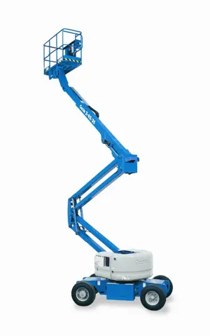
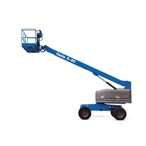
Genie Articulated Boom Lift Z-20N
Need answers fast?
Explore the manual using AI.

The Genie Articulated Boom Lift Z-20N is a versatile aerial work platform designed for enhanced reach and maneuverability. Ideal for construction and maintenance tasks, this model combines robust performance with safety features, ensuring efficient operation in various environments. Trust Genie for reliable access solutions.
Turn manuals into instant answers
with your AI-powered assistantTurn manuals into instant answers
with your AI-powered assistant
Manual for Genie Articulated Boom Lift Z-20N
Complete asset maintenance, one click away
Get instant access to all the maintenance information you need. Empower technicians to perform preventive maintenance with asset packages, ready to use right out of the box.

Documents & Manuals
Find all the essential guides in one place.
 Tensioning Guide
- Belt-diagram
- C-120 pulleys
+ 13 more

Work Order Templates
Pre-built workflows to keep your asset running smoothly.
- Daily Electrical System Inspection
- Replace Roller and Pulley
- Install Engine B-120
+ 29 more

Procedures
Integrate maintenance plans directly into your work orders.
- Motion Industries
- Applied Industrial Technologies
- Electrical Brothers
+ 5 more

Parts
Access the parts list for your equipment in MaintainX.
- Drive Motor
- B2 Rollers
- Tensioning System
+ 40 more
Genie Articulated Boom Lift Z-20N
Create an account to install this asset package.
Maintenance Plans for Genie Articulated Boom Lift Model Z-20N
Integrate maintenance plans directly into your work orders in MaintainX.
1000 Hourly Drive Hub Oil Replacement
- Replace the Drive Hub Oil
Drive hub specifications require that this procedure be performed after the first 50 hours of operation
After the initial oil replacement, specifications require that this procedure be performed every 1000 hours
Replacing the drive hub oil is essential for good machine performance and service life. Failure to replace the drive hub oil may cause the machine to perform poorly and continued use may cause component damage
Drive Hubs:
1. Select the drive hub to be serviced. Drive the machine until one of the two plugs is at the lowest point
2. Remove the plugs and drain the oil into a suitable container
3. Drive the machine until one of the two plugs is at the highest point
4. Drive hubs with 2 plugs: Fill the hub until the oil level is even with the bottom of the lowest plug hole. Refer to Specifications, Hydraulic Specifications

50 Hourly Track Tension and Fastener Torque Check
- Check the Track Tension and Fastener Torque, TRAX Models - S-40 and S-45 Models
Maintaining proper track tension and properly torqued fasteners is essential to good machine performance and service life; The machine will not operate properly with a track that is incorrectly tensioned. Continued use of a machine with incorrectly tensioned tracks may cause component damage
1. Thoroughly clean the track assembly of any dirt, rocks, clay, etc.
2. Chock the tracks at one end of the machine to prevent the machine from rolling
3. Center a lifting jack of ample capacity (20,000 Ibs / 10,000 kg) under the drive chassis between the tracks at the other end of the machine
4. Lift the machine until the tracks are off the ground and then place jack stands under the drive chassis for support
5. Visually inspect the section of track under the bogey wheels
Result: There should be less than 1 inch / 2.5 cm of gap between the bogey wheels and the inside surface of the track. Proceed to step 7
Result: There is 1 inch / 2.5 cm or more of gap between the bogey wheels and the inside surface of the track. Proceed to step 6
3 Monthly Boom Angle Sensor Test
- Test the Primary Boom Angle Sensor - SX-105 XC, SX-125 XC, SX-135 XC, SX-150 and SX-180
A properly functioning primary boom angle sensor is essential to safe machine operation. The ECM at the ground controls (TCON) monitors the position and angle of the primary boom using the signal from the primary boom angle sensor
The primary boom angle sensor signal is used to control the ramping of the primary boom, limiting the speed of the primary boom to 2.3 feet / 0.7 meters per second
Note: The turntable level sensor must be tested before starting this procedure. Refer to Maintenance Procedures, Test the Turntable Level Sensor
Note: A digital level will be required to perform this procedure
Note: A kit is available through Genie Product Support (Genie part number 58351). This kit includes a digital level with a magnetic base and cable harnesses
Note: A properly calibrated digital level is essential to proper machine calibration. Refer to the manufactures calibration information
Note: Use the following chart to identify the description of each LCD screen control button used in this procedure
Note: Perform this procedure with the booms in the fully stowed position and the axles fully extended
3 Monthly Recovery System Test
This maintenance procedure applies to the following models: S-100, S-105, S-120, S-125, S-100HD, S-120HD, SX-105 XC, SX-125 XC, SX-135 XC, SX-150, SX-180, Z-80/60, Z-135/70 and ZX-135/70
Perform this procedure with the machine on a firm, level surface with the axles extended
Perform this procedure with all weight, tools, equipment and personnel removed from the platform
If any boom safety limit switches are faulty, the primary boom will only retract and not lower
Turn the key switch to the ground control and pull out the red Emergency Stop button to the on position. Start the engine
Fully raise the secondary boom then extend it approximately 4 ft / 1.2 m
Raise the primary boom approximately 15° then extend it approximately 4 ft / 1.2 m
Turn the key switch to the off position to turn off the engine. Turn the key switch back to ground controls
Remove the key from the main key switch and insert the key into the bypass/recovery key switch
3 Monthly Safety Envelope Limit Switch Test
- Test the Safety Envelope Limit Switches, Z-135/70, ZX-135/70, SX-105 XC, SX-125 XC, SX-135 XC, SX-150 and SX-180 Models
Testing the machine envelope safety limit switches is critical to safe machine operation. If the boom is allowed to operate when a safety switch is not functioning correctly, the machine stability could be compromised and may tip over
Note: Perform this procedure with the boom in the stowed position
Note: Perform this procedure with the axles extended
Note: Two people will be required to perform this procedure
Note: Use the following chart to identify the description of each LCD screen control button used in this procedure
Z-135/70 and ZX-135/70 Models:
Secondary Boom #1 Retracted Safety Limit Switch, LSS1RS
1. Working at the platform end of the turntable, support and secure the lower turntable riser end cover to a suitable lifting device
Parts for Genie Articulated Boom Lift Z-20N
Access the parts list for your equipment in MaintainX.
O-ring Field Service Kit
49612
Digital Level Kit
58351
Digital Protractor
58377
O-ring Field Service Kit
49612
Digital Level Kit
58351
Digital Protractor
58377
O-ring Field Service Kit
49612
Digital Level Kit
58351
Digital Protractor
58377
Unlock efficiency
with MaintainX CoPilot
MaintainX CoPilot is your expert colleague, on call 24/7, helping your team find the answers they need to keep equipment running.
Reduce Unplanned Downtime
Ensure your team follows consistent procedures to minimize equipment failures and costly delays.
Maximize Asset Availability
Keep your assets running longer and more reliably, with standardized maintenance workflows from OEM manuals.
Lower Maintenance Costs
Turn any technician into an expert to streamline operations, maintain more assets, and reduce overall costs.
Thousands of companies manage their assets with MaintainX

'%3e%3cpath%20fill='url(%23b)'%20d='M66.008%2080.068c-5.084-.786-9.763-3.834-12.442-8.68a16.942%2016.942%200%200%201-1.87-5.18c1.096.19%202.203.476%203.298.87%206.525%202.333%2010.836%207.68%2011.014%2012.99ZM51.47%2061.576c.488-5.524%203.62-10.716%208.847-13.597a17.132%2017.132%200%200%201%2011.335-1.882c-.798%208.145-7.43%2014.848-16.038%2015.599-1.417.119-2.799.07-4.144-.12Zm28.564-11.478a17.513%2017.513%200%200%201%203.727%204.62c4.608%208.335%201.584%2018.813-6.75%2023.409a16.988%2016.988%200%200%201-4.359%201.679%2019.624%2019.624%200%200%201-3.977-12.776c.346-7.561%204.942-13.931%2011.36-16.932Z'/%3e%3cpath%20fill='%23110F0D'%20fill-rule='evenodd'%20d='M142.831%2048.324h4.977V77.03h-4.977V48.324Zm27.278%2013.002c.322%201.048.453%202.263.453%203.62v12.073h-4.787V66.208c0-.75-.047-1.572-.154-2.143-.453-2.382-1.822-3.572-4.215-3.572-2.31%200-3.882%201.274-4.43%203.476-.143.596-.226%201.405-.226%202.25v10.8h-4.787V56.623h4.477v2.989c1.536-2.5%203.906-3.43%206.371-3.43%203.488%200%206.263%201.68%207.298%205.144Zm24.636%207.323c0%203.882-2.358%206.525-5.763%207.727-1.298.453-2.632.643-4.62.643h-10.169V48.324h9.085c1.691%200%203.156.143%204.049.38%203.465.93%205.727%203.68%205.727%207.335%200%202.441-.81%204.156-2.762%205.644%202.905%201.417%204.453%203.727%204.453%206.966Zm-15.634-8.656h4.584c1.024%200%201.917-.143%202.536-.417%201.215-.548%201.905-1.608%201.905-3.167%200-1.548-.643-2.572-1.845-3.132-.691-.31-1.762-.452-2.763-.452h-4.417v7.168Zm10.716%208.465c0-1.536-.893-3.37-3.227-3.893-.428-.095-1.036-.143-1.571-.143h-5.918v8.085h5.501c.56%200%201.429-.048%201.953-.167%201.94-.453%203.262-1.846%203.262-3.882Zm47.747-11.847-8.097%2020.408h-4.429l-8.109-20.408h5.191l5.192%2014.574%205.108-14.574h5.144Zm-20.218%2010.002c0%20.69-.036%201.262-.155%201.94h-15.943c.631%202.87%202.714%204.728%205.882%204.728%202.131%200%203.607-.882%204.703-2.525h4.87c-1.762%204.144-5.204%206.692-9.657%206.692-6.084%200-10.537-4.858-10.537-10.49%200-6.108%204.524-10.776%2010.335-10.776%206.239%200%2010.442%204.954%2010.502%2010.43Zm-4.763-1.405c-.333-2.846-2.643-4.858-5.691-4.858-2.894%200-5.287%201.929-5.621%204.858h11.312Zm-72.667%203.44c0%204.787-3.287%208.371-9.419%208.371H119.363V64.66c-1.917.274-3.87.69-5.811%201.238l4.537%2011.121h-5.418l-3.596-9.585c-5.144%202.084-10.085%205.216-14.217%209.585h-4.786L101.8%2048.312h4.56l5.68%2013.883a44.112%2044.112%200%200%201%207.323-1.774V48.312h9.084c1.703%200%203.156.143%204.061.393%203.453.929%205.727%203.667%205.727%207.323%200%201.917-.738%204.179-2.81%205.691%203.06%201.56%204.501%204.025%204.501%206.93Zm-15.634-8.667a62.664%2062.664%200%200%201%202.06-.036c1.703.012%203.239.131%204.608.37%201.441-.549%202.357-1.727%202.357-3.537%200-1.941-.881-3.144-2.488-3.667-.548-.18-1.358-.286-2.322-.286h-4.215v7.156Zm-16.55%203.905-3.715-9.894-6.394%2016.502c2.833-2.595%206.263-4.858%2010.109-6.608Zm27.254%204.74c0-2.775-3.131-4.347-8.513-4.418-.715%200-1.441.011-2.191.047v8.252h5.918c2.548%200%204.786-1.37%204.786-3.882Z'%20clip-rule='evenodd'/%3e%3c/g%3e%3cdefs%3e%3clinearGradient%20id='b'%20x1='51.47'%20x2='85.916'%20y1='62.946'%20y2='62.946'%20gradientUnits='userSpaceOnUse'%3e%3cstop%20stop-color='%23CD9F28'/%3e%3cstop%20offset='1'%20stop-color='%23ECD80B'/%3e%3c/linearGradient%3e%3cclipPath%20id='a'%3e%3cpath%20fill='%23fff'%20d='M51.47%2045.728h186.104V80.14H51.47z'/%3e%3c/clipPath%3e%3c/defs%3e%3c/svg%3e)


More from Genie


Explore Other Assets


© 2026 MaintainX. All rights reserved.