


Caterpillar Wheel Loader 980K
Need answers fast?
Explore the manual using AI.
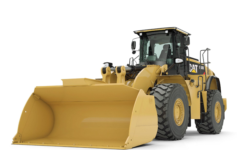
The Caterpillar Wheel Loader 980K is a robust and versatile piece of heavy machinery designed for various industrial applications. Known for its powerful performance and durability, this model excels in material handling, construction, and mining operations, making it an essential asset for any fleet.
Turn manuals into instant answers
with your AI-powered assistantTurn manuals into instant answers
with your AI-powered assistant
Manual for Caterpillar Wheel Loader 980K
Complete asset maintenance, one click away
Get instant access to all the maintenance information you need. Empower technicians to perform preventive maintenance with asset packages, ready to use right out of the box.

Documents & Manuals
Find all the essential guides in one place.
 Tensioning Guide
- Belt-diagram
- C-120 pulleys
+ 13 more

Work Order Templates
Pre-built workflows to keep your asset running smoothly.
- Daily Electrical System Inspection
- Replace Roller and Pulley
- Install Engine B-120
+ 29 more

Procedures
Integrate maintenance plans directly into your work orders.
- Motion Industries
- Applied Industrial Technologies
- Electrical Brothers
+ 5 more

Parts
Access the parts list for your equipment in MaintainX.
- Drive Motor
- B2 Rollers
- Tensioning System
+ 40 more
Caterpillar Wheel Loader 980K
Create an account to install this asset package.
Maintenance Plans for Caterpillar Wheel Loader Model 980K
Integrate maintenance plans directly into your work orders in MaintainX.
Heater Preparation
Remove Access Door and side panel.
Heater Mounting Location (Left side of machine)
Obtain fuse box access by removing interior panels shown.
IMPORTANT: The CAT 980K Series is designed with a negative (Ground) master disconnect switch. The proceeding steps will describe a necessary Webasto harness ground modification required for this installation.
Remove the heater electrical connector from its current mounting location. This will be relocated in proceeding steps.
Remove ground portion of the harness from the location shown.
Reconfigure all heater harness ground leads into one spliced ground circuit. Harness will no longer be grounded to the heater or machine chassis.
During the heater dry fit mounting process; mark and drill a new hole to mount the electrical connector bracket facing the front of the machine.
Rear heater mounting bracket.;

Heater Mounting
The heater is installed on the left side of the machine to the frame structure using existing mounting points as shown in figures 15-17.
Remove the two existing O.E. bolts and mount large bracket to frame using item 5 of the Optional Add-on Accessories section on page 5. Use one of the previously removed O.E. bolts to affix the small bracket to inner frame shown in fig. 16-17.
A mounting bracket must be fabricated by the installer. Refer to section 6 for mounting bracket example.;
Heater Electrical Installation
Route the Webasto power harness (Red and Brown 10 gauge wires) from the heater towards the front of the machine and around the back side of the engine.
WARNING:
Make sure to turn off master disconnect switch before performing this step!
Locate the starter motor on the right side of the engine. Cut the positive lead of the Webasto heater harness to proper length, install supplied eyelet and connect to starter stud as shown in fig. 20.
Route the Webasto heater harness (Brown) ground wire to the engine ground stud as shown. Cut to length, install eyelet and connect to stud as shown in fig. 21.
To enter the cab with the Webasto controller harness; locate existing CAT connector in the back left corner of cab. Use the Deutsch terminals listed in the parts section to pin the 4 controller wires (white, green, black, and red) and insert into the 4 unused sockets of the connector. In this installation, pins 8-11 were empty.
Locate the same connector from the inside of the cab (left rear corner) and pin the remainder of the Webasto controller harness to match the wire colors from the previous step.
Mount the SmarTemp Control fx as shown in fig. 24.
Route controller harness to front right windshield pillar and connect using the pin-out chart below.;
Heater Fuel Installation
Remove the left side step panel per manufacturer’s recommendations to access the top of the fuel tank.
Thoroughly clean all debris around fuel tank access cover.
Remove for fuel standpipe installation in proceeding steps.
NOTE:
There is an O-ring seal between the access cover and the fuel tank. If the access cover is carefully removed and the seal remains tacked to the cover, it’s possible to reuse the seal. If this O-ring seal becomes damaged or warped in any way it must be replaced.
- Secure fuel tank access cover using a vice or comparable tool.
- Locate the center of the access cover and drill and tap using a 3/8” drill bit and ¼-18 pipe tap.
IMPORTANT:
Make sure the tapered (Pipe) tap is used when tapping this hole as a standard tap will not allow for a fuel tight fit.
Hydra liner Hydraulic Fluid Warmer Installation
Remove The hydraulic tank per manufacturer’s recommendations.
Locate the rearmost lower left corner of the hydraulic tank. Using the proper safety equipment, carefully remove the retaining bracket with a grinding wheel.
From the forward most side of the tank, remove the access cover.
IMPORTANT: Never re-use the access cover gasket. Be sure to have the correct gasket on hand when removing this access panel.
Using the dimensions in fig. 42, locate the center point and clearly mark.
Using the proper safety equipment, drill a 3” O.D. hole using a hole saw.
Install the coupler so that the Hydra Liner is a minimum of 1” from the opposite wall of the coupler installation.
For example this installation required the coupler to be welded and gusseted with approximately a 1” lip on the outside of the tank. This maintained the proper 1” distance from the rear wall when the Hydra Liner was completely tightened into place.
IMPORTANT: Thoroughly clean all debris from the inside of the tank, install a new access cover gasket and reinstall the hydraulic tank.;
Parts for Caterpillar Wheel Loader 980K
Access the parts list for your equipment in MaintainX.
Deutsch Terminal Crimping Tool (Optional)
HDT-48-00
Deutsch Plug (20-16 Gauge)
901202
Deutsch Plug (20-16 Gauge)
0460-202-16141
Weld-on Adapter Coupler
A-3228HD
Bracket Mounting Bolt - Zinc Plate M14 x 40 (8.8)
BCT010079A
Deutsch Terminal Crimping Tool (Optional)
HDT-48-00
Deutsch Plug (20-16 Gauge)
901202
Deutsch Plug (20-16 Gauge)
0460-202-16141
Weld-on Adapter Coupler
A-3228HD
Bracket Mounting Bolt - Zinc Plate M14 x 40 (8.8)
BCT010079A
Deutsch Terminal Crimping Tool (Optional)
HDT-48-00
Deutsch Plug (20-16 Gauge)
901202
Deutsch Plug (20-16 Gauge)
0460-202-16141
Weld-on Adapter Coupler
A-3228HD
Bracket Mounting Bolt - Zinc Plate M14 x 40 (8.8)
BCT010079A
Unlock efficiency
with MaintainX CoPilot
MaintainX CoPilot is your expert colleague, on call 24/7, helping your team find the answers they need to keep equipment running.
Reduce Unplanned Downtime
Ensure your team follows consistent procedures to minimize equipment failures and costly delays.
Maximize Asset Availability
Keep your assets running longer and more reliably, with standardized maintenance workflows from OEM manuals.
Lower Maintenance Costs
Turn any technician into an expert to streamline operations, maintain more assets, and reduce overall costs.
Thousands of companies manage their assets with MaintainX

'%3e%3cpath%20fill='url(%23b)'%20d='M66.008%2080.068c-5.084-.786-9.763-3.834-12.442-8.68a16.942%2016.942%200%200%201-1.87-5.18c1.096.19%202.203.476%203.298.87%206.525%202.333%2010.836%207.68%2011.014%2012.99ZM51.47%2061.576c.488-5.524%203.62-10.716%208.847-13.597a17.132%2017.132%200%200%201%2011.335-1.882c-.798%208.145-7.43%2014.848-16.038%2015.599-1.417.119-2.799.07-4.144-.12Zm28.564-11.478a17.513%2017.513%200%200%201%203.727%204.62c4.608%208.335%201.584%2018.813-6.75%2023.409a16.988%2016.988%200%200%201-4.359%201.679%2019.624%2019.624%200%200%201-3.977-12.776c.346-7.561%204.942-13.931%2011.36-16.932Z'/%3e%3cpath%20fill='%23110F0D'%20fill-rule='evenodd'%20d='M142.831%2048.324h4.977V77.03h-4.977V48.324Zm27.278%2013.002c.322%201.048.453%202.263.453%203.62v12.073h-4.787V66.208c0-.75-.047-1.572-.154-2.143-.453-2.382-1.822-3.572-4.215-3.572-2.31%200-3.882%201.274-4.43%203.476-.143.596-.226%201.405-.226%202.25v10.8h-4.787V56.623h4.477v2.989c1.536-2.5%203.906-3.43%206.371-3.43%203.488%200%206.263%201.68%207.298%205.144Zm24.636%207.323c0%203.882-2.358%206.525-5.763%207.727-1.298.453-2.632.643-4.62.643h-10.169V48.324h9.085c1.691%200%203.156.143%204.049.38%203.465.93%205.727%203.68%205.727%207.335%200%202.441-.81%204.156-2.762%205.644%202.905%201.417%204.453%203.727%204.453%206.966Zm-15.634-8.656h4.584c1.024%200%201.917-.143%202.536-.417%201.215-.548%201.905-1.608%201.905-3.167%200-1.548-.643-2.572-1.845-3.132-.691-.31-1.762-.452-2.763-.452h-4.417v7.168Zm10.716%208.465c0-1.536-.893-3.37-3.227-3.893-.428-.095-1.036-.143-1.571-.143h-5.918v8.085h5.501c.56%200%201.429-.048%201.953-.167%201.94-.453%203.262-1.846%203.262-3.882Zm47.747-11.847-8.097%2020.408h-4.429l-8.109-20.408h5.191l5.192%2014.574%205.108-14.574h5.144Zm-20.218%2010.002c0%20.69-.036%201.262-.155%201.94h-15.943c.631%202.87%202.714%204.728%205.882%204.728%202.131%200%203.607-.882%204.703-2.525h4.87c-1.762%204.144-5.204%206.692-9.657%206.692-6.084%200-10.537-4.858-10.537-10.49%200-6.108%204.524-10.776%2010.335-10.776%206.239%200%2010.442%204.954%2010.502%2010.43Zm-4.763-1.405c-.333-2.846-2.643-4.858-5.691-4.858-2.894%200-5.287%201.929-5.621%204.858h11.312Zm-72.667%203.44c0%204.787-3.287%208.371-9.419%208.371H119.363V64.66c-1.917.274-3.87.69-5.811%201.238l4.537%2011.121h-5.418l-3.596-9.585c-5.144%202.084-10.085%205.216-14.217%209.585h-4.786L101.8%2048.312h4.56l5.68%2013.883a44.112%2044.112%200%200%201%207.323-1.774V48.312h9.084c1.703%200%203.156.143%204.061.393%203.453.929%205.727%203.667%205.727%207.323%200%201.917-.738%204.179-2.81%205.691%203.06%201.56%204.501%204.025%204.501%206.93Zm-15.634-8.667a62.664%2062.664%200%200%201%202.06-.036c1.703.012%203.239.131%204.608.37%201.441-.549%202.357-1.727%202.357-3.537%200-1.941-.881-3.144-2.488-3.667-.548-.18-1.358-.286-2.322-.286h-4.215v7.156Zm-16.55%203.905-3.715-9.894-6.394%2016.502c2.833-2.595%206.263-4.858%2010.109-6.608Zm27.254%204.74c0-2.775-3.131-4.347-8.513-4.418-.715%200-1.441.011-2.191.047v8.252h5.918c2.548%200%204.786-1.37%204.786-3.882Z'%20clip-rule='evenodd'/%3e%3c/g%3e%3cdefs%3e%3clinearGradient%20id='b'%20x1='51.47'%20x2='85.916'%20y1='62.946'%20y2='62.946'%20gradientUnits='userSpaceOnUse'%3e%3cstop%20stop-color='%23CD9F28'/%3e%3cstop%20offset='1'%20stop-color='%23ECD80B'/%3e%3c/linearGradient%3e%3cclipPath%20id='a'%3e%3cpath%20fill='%23fff'%20d='M51.47%2045.728h186.104V80.14H51.47z'/%3e%3c/clipPath%3e%3c/defs%3e%3c/svg%3e)


More from Caterpillar


Explore Other Assets


© 2026 MaintainX. All rights reserved.