


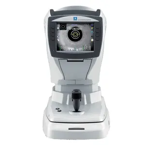
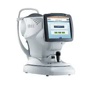
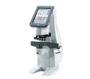
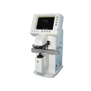
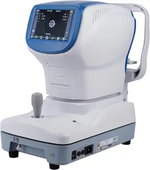
Nidec Automatic Chart Projector CP-690
Need answers fast?
Explore the manual using AI.
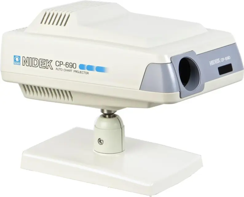
The Nidec Automatic Chart Projector CP-690 is a high-performance projection device designed for precision imaging in various industrial applications. Known for its reliability and advanced optical technology, this model ensures clear and accurate presentations, making it an essential tool for professionals in the field.
Turn manuals into instant answers
with your AI-powered assistantTurn manuals into instant answers
with your AI-powered assistant
Manual for Nidec Automatic Chart Projector CP-690
Complete asset maintenance, one click away
Get instant access to all the maintenance information you need. Empower technicians to perform preventive maintenance with asset packages, ready to use right out of the box.

Documents & Manuals
Find all the essential guides in one place.
 Tensioning Guide
- Belt-diagram
- C-120 pulleys
+ 13 more

Work Order Templates
Pre-built workflows to keep your asset running smoothly.
- Daily Electrical System Inspection
- Replace Roller and Pulley
- Install Engine B-120
+ 29 more

Procedures
Integrate maintenance plans directly into your work orders.
- Motion Industries
- Applied Industrial Technologies
- Electrical Brothers
+ 5 more

Parts
Access the parts list for your equipment in MaintainX.
- Drive Motor
- B2 Rollers
- Tensioning System
+ 40 more
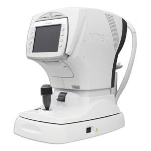
Nidec Automatic Chart Projector CP-690
Create an account to install this asset package.
Maintenance Plans for Nidec Automatic Chart Projector Model CP-690
Integrate maintenance plans directly into your work orders in MaintainX.
Chart ASSY Replacement
Remove the top and bottom cover ASSYs
Disconnect the connector from J3 on the BA01 board
Cut the tie wrap (T18R) which ties the cables of the mask motor
Remove the disk cover (M030)
Unscrew BS3 × 6znc to remove the VA mask (M029)
Unscrew SB3 × 6 (n=2) to remove the illumination ASSY (1200)
Unscrew BS3 × 6znc (n=2) to remove the mask sensor and sensor fitting plate (M009)
Unscrew SB4 × 10 (n=4), SW4 (n=4) and mask sensor and sensor fitting plate M009), PW4 (n=4) to remove the mask ASSY
Loosen HH4 × 6 (n=4) of the chart disk retainer, pull out the chart ASSY from the shaft of the chart motor by sliding the chart ASSY and then insert the new chart ASSY

BA01 Board Replacement
Top cover removed
All connectors from the BA01 board removed
1 chip CPU pulled out from the BA01 board and installed into the new board
NOTE! Be careful of the orientation of the CPU.
BS3 × 10ZnC (n=2) fixing the bridge diode (D1) and regulator IC (IC2) unscrewed
BA01 board removed while holding the tip of the four spacers with long nose pliers and new circuit board mounted
New bridge diode (D1) and regulator IC (IC2) fixed into the radiator plate (M032) with the screws and each terminal soldered onto the BA01 board
Removed parts assembled in reverse order
Sign off on the BA01 board replacement
Holder ASSY Cleaning
Warning: This procedure requires trained personnel with PPE!
Top and front cover ASSYs removed?
Objective holder rotated counterclockwise and removed from the lens barrel?
Surface of the lens of the objective holder cleaned?
For stubborn dirt, use a swab whose tip is wrapped in lens cleaning paper and is dampened with the liquid mixture.
Surface of the lenses indicated by arrows in the diagram cleaned?
Parts assembled in reverse order?
Adjustment of the installed position of the main body and the focus performed according to the operator’s manual?
Sign off on the Holder ASSY Cleaning
BA14 Board Replacement
Warning: Do not conduct work until the device cool down.
Device cooled down?
Top and front cover ASSYs removed?
J2 connector and EA14 cable connector on the BA01 board disconnected?
BA14 board removed and replaced with new one?
New board pushed into the spacers properly?
Removed parts assembled in reverse order?
Sign off on the BA14 board replacement
LED ASSY/C lens ASSY Replacement
Warning: Once the lamp goes on, its surroundings become hot. Do not touch parts near the lamp until they cool down.
Remove the top and bottom cover ASSYs
Remove the cable of the LED ASSY from the BA14 board
Loosen TH3 × 4 (n=3) in order to remove the LED ASSY
Attach the new LED ASSY under the condition that the cable of the LED ASSY is upside
Unscrew SB3 × 6 (n=2) to remove the illumination part ASSY
Loosen TH3 × 4 (n=3) to remove the C lens ASSY
Attach the new C lens ASSY under the condition that the two fix screws, which are on the side of the C lens ASSY, are upside
Assemble the top and bottom cover ASSYs after “6.4 Adjustment of the fixed mask position” and Adjustment of the lamp filament position are performed
Parts for Nidec Automatic Chart Projector CP-690
Access the parts list for your equipment in MaintainX.
Chart
33156-3400
BA01 Board
33155-BA01
Mask
33156-1100
Chart AS
33156-1400
Fuse Slow-blow Type
80402-02037
Chart
33156-3400
BA01 Board
33155-BA01
Mask
33156-1100
Chart AS
33156-1400
Fuse Slow-blow Type
80402-02037
Chart
33156-3400
BA01 Board
33155-BA01
Mask
33156-1100
Chart AS
33156-1400
Fuse Slow-blow Type
80402-02037
Unlock efficiency
with MaintainX CoPilot
MaintainX CoPilot is your expert colleague, on call 24/7, helping your team find the answers they need to keep equipment running.
Reduce Unplanned Downtime
Ensure your team follows consistent procedures to minimize equipment failures and costly delays.
Maximize Asset Availability
Keep your assets running longer and more reliably, with standardized maintenance workflows from OEM manuals.
Lower Maintenance Costs
Turn any technician into an expert to streamline operations, maintain more assets, and reduce overall costs.
Thousands of companies manage their assets with MaintainX

'%3e%3cpath%20fill='url(%23b)'%20d='M66.008%2080.068c-5.084-.786-9.763-3.834-12.442-8.68a16.942%2016.942%200%200%201-1.87-5.18c1.096.19%202.203.476%203.298.87%206.525%202.333%2010.836%207.68%2011.014%2012.99ZM51.47%2061.576c.488-5.524%203.62-10.716%208.847-13.597a17.132%2017.132%200%200%201%2011.335-1.882c-.798%208.145-7.43%2014.848-16.038%2015.599-1.417.119-2.799.07-4.144-.12Zm28.564-11.478a17.513%2017.513%200%200%201%203.727%204.62c4.608%208.335%201.584%2018.813-6.75%2023.409a16.988%2016.988%200%200%201-4.359%201.679%2019.624%2019.624%200%200%201-3.977-12.776c.346-7.561%204.942-13.931%2011.36-16.932Z'/%3e%3cpath%20fill='%23110F0D'%20fill-rule='evenodd'%20d='M142.831%2048.324h4.977V77.03h-4.977V48.324Zm27.278%2013.002c.322%201.048.453%202.263.453%203.62v12.073h-4.787V66.208c0-.75-.047-1.572-.154-2.143-.453-2.382-1.822-3.572-4.215-3.572-2.31%200-3.882%201.274-4.43%203.476-.143.596-.226%201.405-.226%202.25v10.8h-4.787V56.623h4.477v2.989c1.536-2.5%203.906-3.43%206.371-3.43%203.488%200%206.263%201.68%207.298%205.144Zm24.636%207.323c0%203.882-2.358%206.525-5.763%207.727-1.298.453-2.632.643-4.62.643h-10.169V48.324h9.085c1.691%200%203.156.143%204.049.38%203.465.93%205.727%203.68%205.727%207.335%200%202.441-.81%204.156-2.762%205.644%202.905%201.417%204.453%203.727%204.453%206.966Zm-15.634-8.656h4.584c1.024%200%201.917-.143%202.536-.417%201.215-.548%201.905-1.608%201.905-3.167%200-1.548-.643-2.572-1.845-3.132-.691-.31-1.762-.452-2.763-.452h-4.417v7.168Zm10.716%208.465c0-1.536-.893-3.37-3.227-3.893-.428-.095-1.036-.143-1.571-.143h-5.918v8.085h5.501c.56%200%201.429-.048%201.953-.167%201.94-.453%203.262-1.846%203.262-3.882Zm47.747-11.847-8.097%2020.408h-4.429l-8.109-20.408h5.191l5.192%2014.574%205.108-14.574h5.144Zm-20.218%2010.002c0%20.69-.036%201.262-.155%201.94h-15.943c.631%202.87%202.714%204.728%205.882%204.728%202.131%200%203.607-.882%204.703-2.525h4.87c-1.762%204.144-5.204%206.692-9.657%206.692-6.084%200-10.537-4.858-10.537-10.49%200-6.108%204.524-10.776%2010.335-10.776%206.239%200%2010.442%204.954%2010.502%2010.43Zm-4.763-1.405c-.333-2.846-2.643-4.858-5.691-4.858-2.894%200-5.287%201.929-5.621%204.858h11.312Zm-72.667%203.44c0%204.787-3.287%208.371-9.419%208.371H119.363V64.66c-1.917.274-3.87.69-5.811%201.238l4.537%2011.121h-5.418l-3.596-9.585c-5.144%202.084-10.085%205.216-14.217%209.585h-4.786L101.8%2048.312h4.56l5.68%2013.883a44.112%2044.112%200%200%201%207.323-1.774V48.312h9.084c1.703%200%203.156.143%204.061.393%203.453.929%205.727%203.667%205.727%207.323%200%201.917-.738%204.179-2.81%205.691%203.06%201.56%204.501%204.025%204.501%206.93Zm-15.634-8.667a62.664%2062.664%200%200%201%202.06-.036c1.703.012%203.239.131%204.608.37%201.441-.549%202.357-1.727%202.357-3.537%200-1.941-.881-3.144-2.488-3.667-.548-.18-1.358-.286-2.322-.286h-4.215v7.156Zm-16.55%203.905-3.715-9.894-6.394%2016.502c2.833-2.595%206.263-4.858%2010.109-6.608Zm27.254%204.74c0-2.775-3.131-4.347-8.513-4.418-.715%200-1.441.011-2.191.047v8.252h5.918c2.548%200%204.786-1.37%204.786-3.882Z'%20clip-rule='evenodd'/%3e%3c/g%3e%3cdefs%3e%3clinearGradient%20id='b'%20x1='51.47'%20x2='85.916'%20y1='62.946'%20y2='62.946'%20gradientUnits='userSpaceOnUse'%3e%3cstop%20stop-color='%23CD9F28'/%3e%3cstop%20offset='1'%20stop-color='%23ECD80B'/%3e%3c/linearGradient%3e%3cclipPath%20id='a'%3e%3cpath%20fill='%23fff'%20d='M51.47%2045.728h186.104V80.14H51.47z'/%3e%3c/clipPath%3e%3c/defs%3e%3c/svg%3e)


More from Nidec


Explore Other Assets


© 2025 MaintainX. All rights reserved.