


Turn manuals into instant answers
with your AI-powered assistantTurn manuals into instant answers
with your AI-powered assistant
Complete asset maintenance, one click away
Get instant access to all the maintenance information you need. Empower technicians to perform preventive maintenance with asset packages, ready to use right out of the box.

Documents & Manuals
Find all the essential guides in one place.
 Tensioning Guide
- Belt-diagram
- C-120 pulleys
+ 13 more

Work Order Templates
Pre-built workflows to keep your asset running smoothly.
- Daily Electrical System Inspection
- Replace Roller and Pulley
- Install Engine B-120
+ 29 more

Procedures
Integrate maintenance plans directly into your work orders.
- Motion Industries
- Applied Industrial Technologies
- Electrical Brothers
+ 5 more

Parts
Access the parts list for your equipment in MaintainX.
- Drive Motor
- B2 Rollers
- Tensioning System
+ 40 more
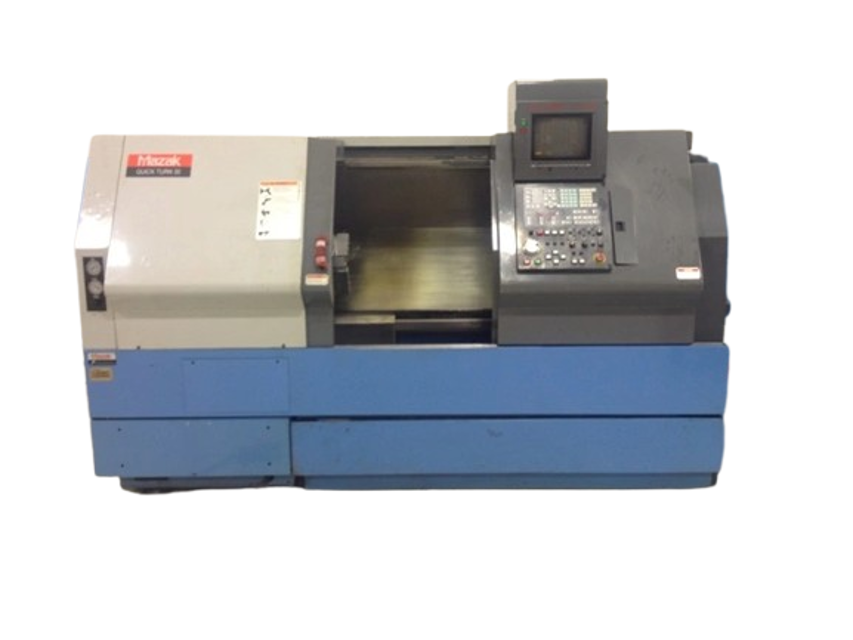
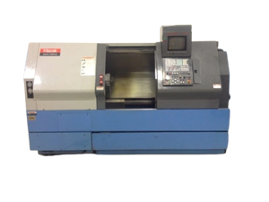
Mazak CNC Machine OTN 250MS
Create an account to install this asset package.
Maintenance Plans for Mazak CNC Machine Model OTN 250MS
Integrate maintenance plans directly into your work orders in MaintainX.
Proximity Sensor Replacement
Remove nuts A and B and remove the sensor
Insert a new sensor into the hole of the bracket
Hand-tighten nuts A and B
Tightening torque at section A: 11.8 N#m (8.7 ft#lbs)
Tightening torque at section B: 19.6 N#m (14.5 ft#lbs)
Measure the clearance between the front end of the sensor and the watchdog
Perform adjustments for a clearance of 0.3 - 0.5 mm (0.01 - 0.02 in.) between the front end of the sensor and the watchdog
To move the sensor forward through 1 mm (0.04 in.): Rotate (loosen) nut A through one counterclockwise turn and Rotate (tighten) nut B through one clockwise turn
To move the sensor backward through 1 mm (0.04 in.): Rotate (loosen) nut B through one counterclockwise turn and Rotate (tighten) nut A through one clockwise turn

X- And Z-Axes Lubrication
Warning: This procedure requires trained personnel with PPE!
Is the greasing pump unit functioning properly?
Enter the hours since the last lubrication
Is the lubricating oil supplied automatically every 30 hours?
Is the lubricating oil supplied automatically with each start of the milling spindle?
Sign off on the X- And Z-Axes Lubrication
Initial 3 Months Hydraulic Unit Maintenance
Inspection when starting hydraulic unit
Check pump rotation direction
Check that the pressure is set to 5 MPa (712 PSI)
Inspection and maintenance of hydraulic unit
CAUTION: When replenishing the hydraulic unit with oil, use only the recommended oil.
Replenish the hydraulic oil when the oil level gauge float is below the center
Replacing the hydraulic oil and cleaning the strainer
CAUTION: Hydraulic oil may be warmed up to high temperature after the continuous operation. Care should be taken not to be get burnt.
Place a container with a capacity of 30 liters (7.93 gal (US)) or so underneath the drain outlet
6 Monthly Tailstock Maintenance
The tailstock is driven by a servomotor via a ball screw. A guide bushing made of resin is mounted at the leading end of the ball screw, and the inside diameter of the pipe connected to the tailstock serves as the guideway for the tailstock to move.
The guide bushing is lubricated with grease and requires checking and regreasing every six months. If unusual operating sounds arise from guide bushing wear, the bushing also needs to be replaced.
1. Checking and regreasing the ball screw guide bushing
(1) Move the tailstock to its minus side and then remove the front cover of the tailstock.
(2) Slide the front cover to the left until the connection between the ball screw and the pipe has come into sight.
(3) Move the tailstock to its home position.
(4) Apply grease to the guide bushing exposed between the supporter and pipe at the connection of the ball screw.
(5) Move the tailstock to its minus side and then remount the front cover.
Note: For recommended grease refer to Subsection 5-6-4.
1 Daily Lubrication Unit Of The Slideway Section Maintenance
1. Inspecting the lubrication unit of the slideway section
A. Inspecting the lubricating oil amount
Before starting the machine every day, check that the lubricating oil reserve tank is filled with the specified lubricating oil to the specified level.
If the oil level is lower than the center of the upper/lower level line of the level gauge at the tank side, supply the same brand of lubricating oil from the oil filter port on the upper part of the lubrication unit so that the oil level do not exceed the upper limit level line.
B. Cleaning and changing the filter
The suction filter in the automatic intermittent lubricating pump can be removed by taking off the screws of the upper part of the pump. The filter on the oil filler port can be removed in the same manner. Clean the filters once in a year.
C. Checking lubricating status
Before starting the day’s operation, check every lubricating status of the lubricating parts. Shortage of oil in the lubricating parts causes clogging of the flow unit and oil leakage from the piping route.
Entry of foreign particles like chips into the flow unit causes clogging and malfunction of the flow unit. In such a case, replace the flow unit.
Parts for Mazak CNC Machine OTN 250MS
Access the parts list for your equipment in MaintainX.
General Safety Instructions
25626328232
Danger Sign For Terminal Box
33116228032
Warning About Each Unit
23116228142
Integrated Warning Plate
23116228252
Warning About Chip Conveyor
33116228381
General Safety Instructions
25626328232
Danger Sign For Terminal Box
33116228032
Warning About Each Unit
23116228142
Integrated Warning Plate
23116228252
Warning About Chip Conveyor
33116228381
General Safety Instructions
25626328232
Danger Sign For Terminal Box
33116228032
Warning About Each Unit
23116228142
Integrated Warning Plate
23116228252
Warning About Chip Conveyor
33116228381
Unlock efficiency
with MaintainX CoPilot
MaintainX CoPilot is your expert colleague, on call 24/7, helping your team find the answers they need to keep equipment running.
Reduce Unplanned Downtime
Ensure your team follows consistent procedures to minimize equipment failures and costly delays.
Maximize Asset Availability
Keep your assets running longer and more reliably, with standardized maintenance workflows from OEM manuals.
Lower Maintenance Costs
Turn any technician into an expert to streamline operations, maintain more assets, and reduce overall costs.
Thousands of companies manage their assets with MaintainX

'%3e%3cpath%20fill='url(%23b)'%20d='M66.008%2080.068c-5.084-.786-9.763-3.834-12.442-8.68a16.942%2016.942%200%200%201-1.87-5.18c1.096.19%202.203.476%203.298.87%206.525%202.333%2010.836%207.68%2011.014%2012.99ZM51.47%2061.576c.488-5.524%203.62-10.716%208.847-13.597a17.132%2017.132%200%200%201%2011.335-1.882c-.798%208.145-7.43%2014.848-16.038%2015.599-1.417.119-2.799.07-4.144-.12Zm28.564-11.478a17.513%2017.513%200%200%201%203.727%204.62c4.608%208.335%201.584%2018.813-6.75%2023.409a16.988%2016.988%200%200%201-4.359%201.679%2019.624%2019.624%200%200%201-3.977-12.776c.346-7.561%204.942-13.931%2011.36-16.932Z'/%3e%3cpath%20fill='%23110F0D'%20fill-rule='evenodd'%20d='M142.831%2048.324h4.977V77.03h-4.977V48.324Zm27.278%2013.002c.322%201.048.453%202.263.453%203.62v12.073h-4.787V66.208c0-.75-.047-1.572-.154-2.143-.453-2.382-1.822-3.572-4.215-3.572-2.31%200-3.882%201.274-4.43%203.476-.143.596-.226%201.405-.226%202.25v10.8h-4.787V56.623h4.477v2.989c1.536-2.5%203.906-3.43%206.371-3.43%203.488%200%206.263%201.68%207.298%205.144Zm24.636%207.323c0%203.882-2.358%206.525-5.763%207.727-1.298.453-2.632.643-4.62.643h-10.169V48.324h9.085c1.691%200%203.156.143%204.049.38%203.465.93%205.727%203.68%205.727%207.335%200%202.441-.81%204.156-2.762%205.644%202.905%201.417%204.453%203.727%204.453%206.966Zm-15.634-8.656h4.584c1.024%200%201.917-.143%202.536-.417%201.215-.548%201.905-1.608%201.905-3.167%200-1.548-.643-2.572-1.845-3.132-.691-.31-1.762-.452-2.763-.452h-4.417v7.168Zm10.716%208.465c0-1.536-.893-3.37-3.227-3.893-.428-.095-1.036-.143-1.571-.143h-5.918v8.085h5.501c.56%200%201.429-.048%201.953-.167%201.94-.453%203.262-1.846%203.262-3.882Zm47.747-11.847-8.097%2020.408h-4.429l-8.109-20.408h5.191l5.192%2014.574%205.108-14.574h5.144Zm-20.218%2010.002c0%20.69-.036%201.262-.155%201.94h-15.943c.631%202.87%202.714%204.728%205.882%204.728%202.131%200%203.607-.882%204.703-2.525h4.87c-1.762%204.144-5.204%206.692-9.657%206.692-6.084%200-10.537-4.858-10.537-10.49%200-6.108%204.524-10.776%2010.335-10.776%206.239%200%2010.442%204.954%2010.502%2010.43Zm-4.763-1.405c-.333-2.846-2.643-4.858-5.691-4.858-2.894%200-5.287%201.929-5.621%204.858h11.312Zm-72.667%203.44c0%204.787-3.287%208.371-9.419%208.371H119.363V64.66c-1.917.274-3.87.69-5.811%201.238l4.537%2011.121h-5.418l-3.596-9.585c-5.144%202.084-10.085%205.216-14.217%209.585h-4.786L101.8%2048.312h4.56l5.68%2013.883a44.112%2044.112%200%200%201%207.323-1.774V48.312h9.084c1.703%200%203.156.143%204.061.393%203.453.929%205.727%203.667%205.727%207.323%200%201.917-.738%204.179-2.81%205.691%203.06%201.56%204.501%204.025%204.501%206.93Zm-15.634-8.667a62.664%2062.664%200%200%201%202.06-.036c1.703.012%203.239.131%204.608.37%201.441-.549%202.357-1.727%202.357-3.537%200-1.941-.881-3.144-2.488-3.667-.548-.18-1.358-.286-2.322-.286h-4.215v7.156Zm-16.55%203.905-3.715-9.894-6.394%2016.502c2.833-2.595%206.263-4.858%2010.109-6.608Zm27.254%204.74c0-2.775-3.131-4.347-8.513-4.418-.715%200-1.441.011-2.191.047v8.252h5.918c2.548%200%204.786-1.37%204.786-3.882Z'%20clip-rule='evenodd'/%3e%3c/g%3e%3cdefs%3e%3clinearGradient%20id='b'%20x1='51.47'%20x2='85.916'%20y1='62.946'%20y2='62.946'%20gradientUnits='userSpaceOnUse'%3e%3cstop%20stop-color='%23CD9F28'/%3e%3cstop%20offset='1'%20stop-color='%23ECD80B'/%3e%3c/linearGradient%3e%3cclipPath%20id='a'%3e%3cpath%20fill='%23fff'%20d='M51.47%2045.728h186.104V80.14H51.47z'/%3e%3c/clipPath%3e%3c/defs%3e%3c/svg%3e)


More from Mazak


Explore Other Assets


© 2026 MaintainX. All rights reserved.