


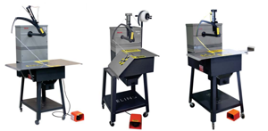
Felins Tying Machine 2000-16
Need answers fast?
Explore the manual using AI.

Turn manuals into instant answers
with your AI-powered assistantTurn manuals into instant answers
with your AI-powered assistant
Manual for Felins Tying Machine 2000-16
Complete asset maintenance, one click away
Get instant access to all the maintenance information you need. Empower technicians to perform preventive maintenance with asset packages, ready to use right out of the box.

Documents & Manuals
Find all the essential guides in one place.
 Tensioning Guide
- Belt-diagram
- C-120 pulleys
+ 13 more

Work Order Templates
Pre-built workflows to keep your asset running smoothly.
- Daily Electrical System Inspection
- Replace Roller and Pulley
- Install Engine B-120
+ 29 more

Procedures
Integrate maintenance plans directly into your work orders.
- Motion Industries
- Applied Industrial Technologies
- Electrical Brothers
+ 5 more

Parts
Access the parts list for your equipment in MaintainX.
- Drive Motor
- B2 Rollers
- Tensioning System
+ 40 more
Felins Tying Machine 2000-16
Create an account to install this asset package.
Maintenance Plans for Felins Tying Machine Model 2000-16
Integrate maintenance plans directly into your work orders in MaintainX.
4 Weekly Moderate Duty Lubrication
Refer to the lubrication photos for lubrication points for oil and grease. Most, but not all, of the lubrication points are highlighted on the machine with white paint.
Lubricate the machine as presented in the Lubrication Schedule.
The following locations are lubricated with 2 - 3 drops of Felins lubricating oil (Part No. 300A03024):
Oil hole for main shaft at base of column - Figure 23
Oil hole for main shaft in shaft support - Figure 24
Oil hole for stripper pivot - Figure 25
Oil hole for tucker pivot - Figure 25
Oil hole in cam follower roller - Figure 26
Base of knotter at top of main frame - Figure 27

Tying Material Tension Adjustment
Warning: Only trained personnel should perform this procedure.
Loosen the brass locknut on the Twine Arrestor.
Choose the direction to turn the black plastic head on the Twine Arrestor
Number of 1/8 turn increments made
Tie a package to confirm that the tension is as desired.
Re-tighten the brass lock nut.
Sign off on the tension adjustment
2 Weekly Heavy Duty Lubrication
Refer to the lubrication photos for lubrication points for oil and grease. Most, but not all, of the lubrication points are highlighted on the machine with white paint. Lubricate the machine as presented in the Lubrication Schedule.
Oil Lubrication Points
The following locations are lubricated with 2 - 3 drops of Felins lubricating oil (Part No. 300A03024):
• Oil hole for main shaft at base of column - Figure 23
• Oil hole for main shaft in shaft support - Figure 24
• Oil hole for stripper pivot - Figure 25
• Oil hole for tucker pivot - Figure 25
• Oil hole in cam follower roller - Figure 26
• Base of knotter at top of main frame - Figure 27
Knotter Plate Spring Adjustment
WARNING: Do not perform maintenance on machinery unless electrical power and air are disconnected, locked out or cannot be turned on by any person other than the individual performing the maintenance.
Disconnect the power at the power switch and remove the power cord.
Remove the screws that secure the table to the machine and remove the table.
Loosen the nylon lock nut to allow the brass nut to be adjusted.
Rotate the brass nut
CAUTION: When operating the machine, the operator should wear appropriate personal protective equipment including, but not limited to safety glasses. The operator should keep hands, any loose clothing or jewelry, and long hair clear of openings and moving parts at all times.
Turn the power back on and test the machine.
NOTE: If further adjustments are needed, make sure to shut off the electrical power and remove the power cord from the machine before continuing with the adjustment process.
Repeat the adjustment procedures as needed.
Tying Material Cutting Knife Replacement
WARNING: Do not perform maintenance on machinery unless electrical power and air are disconnected, locked out or cannot be turned on by any person other than the individual performing the maintenance.
Disconnect the power at the power switch and remove the power cord.
Remove the screws that secure the table to the machine and remove the table.
CAUTION: Even if the knife is not cutting properly, the cutting edge is still extremely sharp. Use extreme caution when handling or working around the knife to avoid injury.
Loosen the two screws securing the knife to the stripper plate. Note: Removing screws completely is not required.
Remove the knife from the stripper plate.
Install new knife making sure to seat the knife all the way back and in the orientation shown.
Tighten the screws.
Reinstall and secure the table.
Parts for Felins Tying Machine 2000-16
Access the parts list for your equipment in MaintainX.
Knife
300A00106
R.H. String Holder Plate
300A00119
L.H. String Holder Plate
300A00120
String Holder Tucker
300A00117
#1 Taper Pin (Not Required On Tandem Models)
900A00015
Knife
300A00106
R.H. String Holder Plate
300A00119
L.H. String Holder Plate
300A00120
String Holder Tucker
300A00117
#1 Taper Pin (Not Required On Tandem Models)
900A00015
Knife
300A00106
R.H. String Holder Plate
300A00119
L.H. String Holder Plate
300A00120
String Holder Tucker
300A00117
#1 Taper Pin (Not Required On Tandem Models)
900A00015
Unlock efficiency
with MaintainX CoPilot
MaintainX CoPilot is your expert colleague, on call 24/7, helping your team find the answers they need to keep equipment running.
Reduce Unplanned Downtime
Ensure your team follows consistent procedures to minimize equipment failures and costly delays.
Maximize Asset Availability
Keep your assets running longer and more reliably, with standardized maintenance workflows from OEM manuals.
Lower Maintenance Costs
Turn any technician into an expert to streamline operations, maintain more assets, and reduce overall costs.
Thousands of companies manage their assets with MaintainX

'%3e%3cpath%20fill='url(%23b)'%20d='M66.008%2080.068c-5.084-.786-9.763-3.834-12.442-8.68a16.942%2016.942%200%200%201-1.87-5.18c1.096.19%202.203.476%203.298.87%206.525%202.333%2010.836%207.68%2011.014%2012.99ZM51.47%2061.576c.488-5.524%203.62-10.716%208.847-13.597a17.132%2017.132%200%200%201%2011.335-1.882c-.798%208.145-7.43%2014.848-16.038%2015.599-1.417.119-2.799.07-4.144-.12Zm28.564-11.478a17.513%2017.513%200%200%201%203.727%204.62c4.608%208.335%201.584%2018.813-6.75%2023.409a16.988%2016.988%200%200%201-4.359%201.679%2019.624%2019.624%200%200%201-3.977-12.776c.346-7.561%204.942-13.931%2011.36-16.932Z'/%3e%3cpath%20fill='%23110F0D'%20fill-rule='evenodd'%20d='M142.831%2048.324h4.977V77.03h-4.977V48.324Zm27.278%2013.002c.322%201.048.453%202.263.453%203.62v12.073h-4.787V66.208c0-.75-.047-1.572-.154-2.143-.453-2.382-1.822-3.572-4.215-3.572-2.31%200-3.882%201.274-4.43%203.476-.143.596-.226%201.405-.226%202.25v10.8h-4.787V56.623h4.477v2.989c1.536-2.5%203.906-3.43%206.371-3.43%203.488%200%206.263%201.68%207.298%205.144Zm24.636%207.323c0%203.882-2.358%206.525-5.763%207.727-1.298.453-2.632.643-4.62.643h-10.169V48.324h9.085c1.691%200%203.156.143%204.049.38%203.465.93%205.727%203.68%205.727%207.335%200%202.441-.81%204.156-2.762%205.644%202.905%201.417%204.453%203.727%204.453%206.966Zm-15.634-8.656h4.584c1.024%200%201.917-.143%202.536-.417%201.215-.548%201.905-1.608%201.905-3.167%200-1.548-.643-2.572-1.845-3.132-.691-.31-1.762-.452-2.763-.452h-4.417v7.168Zm10.716%208.465c0-1.536-.893-3.37-3.227-3.893-.428-.095-1.036-.143-1.571-.143h-5.918v8.085h5.501c.56%200%201.429-.048%201.953-.167%201.94-.453%203.262-1.846%203.262-3.882Zm47.747-11.847-8.097%2020.408h-4.429l-8.109-20.408h5.191l5.192%2014.574%205.108-14.574h5.144Zm-20.218%2010.002c0%20.69-.036%201.262-.155%201.94h-15.943c.631%202.87%202.714%204.728%205.882%204.728%202.131%200%203.607-.882%204.703-2.525h4.87c-1.762%204.144-5.204%206.692-9.657%206.692-6.084%200-10.537-4.858-10.537-10.49%200-6.108%204.524-10.776%2010.335-10.776%206.239%200%2010.442%204.954%2010.502%2010.43Zm-4.763-1.405c-.333-2.846-2.643-4.858-5.691-4.858-2.894%200-5.287%201.929-5.621%204.858h11.312Zm-72.667%203.44c0%204.787-3.287%208.371-9.419%208.371H119.363V64.66c-1.917.274-3.87.69-5.811%201.238l4.537%2011.121h-5.418l-3.596-9.585c-5.144%202.084-10.085%205.216-14.217%209.585h-4.786L101.8%2048.312h4.56l5.68%2013.883a44.112%2044.112%200%200%201%207.323-1.774V48.312h9.084c1.703%200%203.156.143%204.061.393%203.453.929%205.727%203.667%205.727%207.323%200%201.917-.738%204.179-2.81%205.691%203.06%201.56%204.501%204.025%204.501%206.93Zm-15.634-8.667a62.664%2062.664%200%200%201%202.06-.036c1.703.012%203.239.131%204.608.37%201.441-.549%202.357-1.727%202.357-3.537%200-1.941-.881-3.144-2.488-3.667-.548-.18-1.358-.286-2.322-.286h-4.215v7.156Zm-16.55%203.905-3.715-9.894-6.394%2016.502c2.833-2.595%206.263-4.858%2010.109-6.608Zm27.254%204.74c0-2.775-3.131-4.347-8.513-4.418-.715%200-1.441.011-2.191.047v8.252h5.918c2.548%200%204.786-1.37%204.786-3.882Z'%20clip-rule='evenodd'/%3e%3c/g%3e%3cdefs%3e%3clinearGradient%20id='b'%20x1='51.47'%20x2='85.916'%20y1='62.946'%20y2='62.946'%20gradientUnits='userSpaceOnUse'%3e%3cstop%20stop-color='%23CD9F28'/%3e%3cstop%20offset='1'%20stop-color='%23ECD80B'/%3e%3c/linearGradient%3e%3cclipPath%20id='a'%3e%3cpath%20fill='%23fff'%20d='M51.47%2045.728h186.104V80.14H51.47z'/%3e%3c/clipPath%3e%3c/defs%3e%3c/svg%3e)


More from Felins


Explore Other Assets


© 2026 MaintainX. All rights reserved.