


Doosan Lathe LYNX 220M
Need answers fast?
Explore the manual using AI.
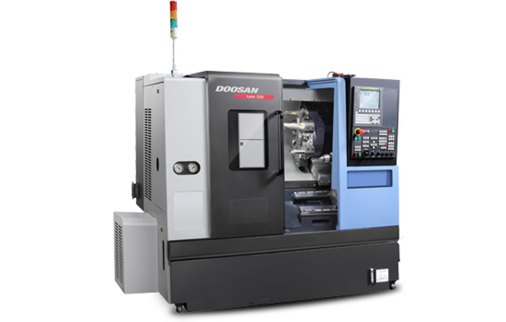
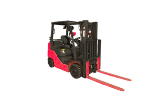
The Doosan Lathe LYNX 220M is a high-performance CNC lathe designed for precision machining. Known for its robust construction and advanced technology, this model enhances productivity and accuracy in various industrial applications. Ideal for manufacturers seeking reliable and efficient turning solutions.
Turn manuals into instant answers
with your AI-powered assistantTurn manuals into instant answers
with your AI-powered assistant
Manual for Doosan Lathe LYNX 220M
Complete asset maintenance, one click away
Get instant access to all the maintenance information you need. Empower technicians to perform preventive maintenance with asset packages, ready to use right out of the box.

Documents & Manuals
Find all the essential guides in one place.
 Tensioning Guide
- Belt-diagram
- C-120 pulleys
+ 13 more

Work Order Templates
Pre-built workflows to keep your asset running smoothly.
- Daily Electrical System Inspection
- Replace Roller and Pulley
- Install Engine B-120
+ 29 more

Procedures
Integrate maintenance plans directly into your work orders.
- Motion Industries
- Applied Industrial Technologies
- Electrical Brothers
+ 5 more

Parts
Access the parts list for your equipment in MaintainX.
- Drive Motor
- B2 Rollers
- Tensioning System
+ 40 more
Doosan Lathe LYNX 220M
Create an account to install this asset package.
Maintenance Plans for Doosan Lathe Model LYNX 220M
Integrate maintenance plans directly into your work orders in MaintainX.
Alignment of Headstock (Main spindle)
Procedure : 1) Loosen the headstock clamping screws(M20, 5 pcs.).
2) Align the headstock
a) In A direction
• After loosening the adjusting screw(b), secure the adjusting screw(a). This shifts the headstock in the A direction.
b) In B direction
• After loosening the adjusting screw(a), secure the adjusting screw(b). This shifts the headstock in the B direction.
• Carry out this adjustment while reading the dial indicator applied at the front end of the test piece.
c) After the required accuracy is obtained, tighten the 5 screws for headstock clamping. Note that reading of the dial indicator applied at the test piece top end must not change.;

Coolant Tank Cleaning
Warning: Ensure the pump is turned off before starting the cleaning process.
Cover at the side of the coolant pump removed
Coolant drawn out of the tank by the pump
Coolant tank pulled out to the right until the pump protrudes from the side cover
Coolant tank pulled out to the front
Inside of the coolant tank cleaned
Filter cleaned
Coolant tank reinstalled correctly
Caution: The coolant tank must not protrude from the front rail. If the coolant tank is not installed correctly, coolant will leak.
Lathe Lubrication
NOTICE! The machine should be completely and correctly lubricated in strict adherence to the directions in the Lubrication Chart in the following page.
Is the specified lubrication oil used?
Is the specified coolant used?
Is the amount of lubricating oil and its discharge condition checked everyday?
Note 1: We do not have any experience in using the oils other than those indicated by an asterisk(*). Selection should thus be made from them. Because slide-way lubricating oil contains additives such as extreme-pressure additive, it could incur variety of troubles if reacting with other oils or coolant. Therefore, pay special attention to the use of slide way lubricating oil.
Note 2: As for service point or amount of lubricating oil of the machine, refer to the Instruction Manual of respective machine models.
Note 3 : Lubricating oil used in common with coolant or lubricating oil used in common with hydraulic oil might cause corrosion of lubrication unit or turbidness of oils to result in lubrication failure, which, in turn, leads to damages on the slideway surface or ball screw. (We take no responsibility for the troubles caused by using the lubricating oil which is not our recommendation.)
Note 4: As for oil replenishment for the optional accessories such as special chucks or chip conveyor, refer to the Special Instruction Manual supplied with individual accessories.
Note 5: When slideway lubricating oil mixed with coolant and some trouble appears, contact your local DOOSAN Infracore representatives. They have optional accessories such as oil skimmer.
6 Monthly Lathe Inspection
Check the wipers for abnormalities such as damage
Check the strainers
Replace the hydraulic oil
Check for oil leakage and for damaged piping
Check the Air unit element and if necessary, replace
Check the electrical components for dirt and discoloration and check for loose terminal screws
Check for loose connector/terminals between units
Sign off on the 6 Monthly Lathe Inspection
Tapered Gibs on Tailstock Base Adjustment
• The machine is shipped after complete adjustment of tapered gibs. Readjustment will become necessary when the gibs are worn or loosened by use, resulting in noticeable irregular feed movement, which adversely affects the working accuracy.
• Adjust the gib using the adjusting screws on right side of the saddle after removing the right and left saddle wipers.
(1) Gib adjustment procedure
a) Loosen the gib adjusting screw at counterclockwise(CCW).
b) Fully tighten at clockwise(CW) and then return by a half turn the gib adjusting screw.
c) Tighten the gib adjusting screw at clockwise(CW).
• Target clearance should be 0.01 mm (0.0004 in.).
d) Adjust the gib of tailstock in the same method.;
Unlock efficiency
with MaintainX CoPilot
MaintainX CoPilot is your expert colleague, on call 24/7, helping your team find the answers they need to keep equipment running.
Reduce Unplanned Downtime
Ensure your team follows consistent procedures to minimize equipment failures and costly delays.
Maximize Asset Availability
Keep your assets running longer and more reliably, with standardized maintenance workflows from OEM manuals.
Lower Maintenance Costs
Turn any technician into an expert to streamline operations, maintain more assets, and reduce overall costs.
Thousands of companies manage their assets with MaintainX

'%3e%3cpath%20fill='url(%23b)'%20d='M66.008%2080.068c-5.084-.786-9.763-3.834-12.442-8.68a16.942%2016.942%200%200%201-1.87-5.18c1.096.19%202.203.476%203.298.87%206.525%202.333%2010.836%207.68%2011.014%2012.99ZM51.47%2061.576c.488-5.524%203.62-10.716%208.847-13.597a17.132%2017.132%200%200%201%2011.335-1.882c-.798%208.145-7.43%2014.848-16.038%2015.599-1.417.119-2.799.07-4.144-.12Zm28.564-11.478a17.513%2017.513%200%200%201%203.727%204.62c4.608%208.335%201.584%2018.813-6.75%2023.409a16.988%2016.988%200%200%201-4.359%201.679%2019.624%2019.624%200%200%201-3.977-12.776c.346-7.561%204.942-13.931%2011.36-16.932Z'/%3e%3cpath%20fill='%23110F0D'%20fill-rule='evenodd'%20d='M142.831%2048.324h4.977V77.03h-4.977V48.324Zm27.278%2013.002c.322%201.048.453%202.263.453%203.62v12.073h-4.787V66.208c0-.75-.047-1.572-.154-2.143-.453-2.382-1.822-3.572-4.215-3.572-2.31%200-3.882%201.274-4.43%203.476-.143.596-.226%201.405-.226%202.25v10.8h-4.787V56.623h4.477v2.989c1.536-2.5%203.906-3.43%206.371-3.43%203.488%200%206.263%201.68%207.298%205.144Zm24.636%207.323c0%203.882-2.358%206.525-5.763%207.727-1.298.453-2.632.643-4.62.643h-10.169V48.324h9.085c1.691%200%203.156.143%204.049.38%203.465.93%205.727%203.68%205.727%207.335%200%202.441-.81%204.156-2.762%205.644%202.905%201.417%204.453%203.727%204.453%206.966Zm-15.634-8.656h4.584c1.024%200%201.917-.143%202.536-.417%201.215-.548%201.905-1.608%201.905-3.167%200-1.548-.643-2.572-1.845-3.132-.691-.31-1.762-.452-2.763-.452h-4.417v7.168Zm10.716%208.465c0-1.536-.893-3.37-3.227-3.893-.428-.095-1.036-.143-1.571-.143h-5.918v8.085h5.501c.56%200%201.429-.048%201.953-.167%201.94-.453%203.262-1.846%203.262-3.882Zm47.747-11.847-8.097%2020.408h-4.429l-8.109-20.408h5.191l5.192%2014.574%205.108-14.574h5.144Zm-20.218%2010.002c0%20.69-.036%201.262-.155%201.94h-15.943c.631%202.87%202.714%204.728%205.882%204.728%202.131%200%203.607-.882%204.703-2.525h4.87c-1.762%204.144-5.204%206.692-9.657%206.692-6.084%200-10.537-4.858-10.537-10.49%200-6.108%204.524-10.776%2010.335-10.776%206.239%200%2010.442%204.954%2010.502%2010.43Zm-4.763-1.405c-.333-2.846-2.643-4.858-5.691-4.858-2.894%200-5.287%201.929-5.621%204.858h11.312Zm-72.667%203.44c0%204.787-3.287%208.371-9.419%208.371H119.363V64.66c-1.917.274-3.87.69-5.811%201.238l4.537%2011.121h-5.418l-3.596-9.585c-5.144%202.084-10.085%205.216-14.217%209.585h-4.786L101.8%2048.312h4.56l5.68%2013.883a44.112%2044.112%200%200%201%207.323-1.774V48.312h9.084c1.703%200%203.156.143%204.061.393%203.453.929%205.727%203.667%205.727%207.323%200%201.917-.738%204.179-2.81%205.691%203.06%201.56%204.501%204.025%204.501%206.93Zm-15.634-8.667a62.664%2062.664%200%200%201%202.06-.036c1.703.012%203.239.131%204.608.37%201.441-.549%202.357-1.727%202.357-3.537%200-1.941-.881-3.144-2.488-3.667-.548-.18-1.358-.286-2.322-.286h-4.215v7.156Zm-16.55%203.905-3.715-9.894-6.394%2016.502c2.833-2.595%206.263-4.858%2010.109-6.608Zm27.254%204.74c0-2.775-3.131-4.347-8.513-4.418-.715%200-1.441.011-2.191.047v8.252h5.918c2.548%200%204.786-1.37%204.786-3.882Z'%20clip-rule='evenodd'/%3e%3c/g%3e%3cdefs%3e%3clinearGradient%20id='b'%20x1='51.47'%20x2='85.916'%20y1='62.946'%20y2='62.946'%20gradientUnits='userSpaceOnUse'%3e%3cstop%20stop-color='%23CD9F28'/%3e%3cstop%20offset='1'%20stop-color='%23ECD80B'/%3e%3c/linearGradient%3e%3cclipPath%20id='a'%3e%3cpath%20fill='%23fff'%20d='M51.47%2045.728h186.104V80.14H51.47z'/%3e%3c/clipPath%3e%3c/defs%3e%3c/svg%3e)


More from Doosan


Explore Other Assets


© 2026 MaintainX. All rights reserved.