


Caterpillar Forklift E6000
Need answers fast?
Explore the manual using AI.
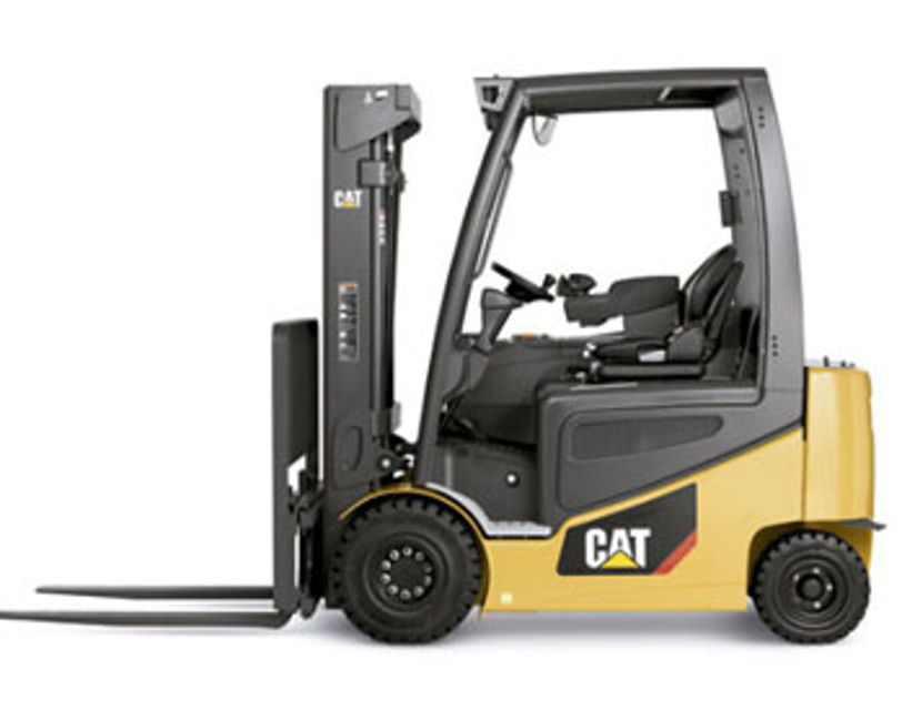
The Caterpillar Forklift E6000 is a robust industrial forklift designed for heavy-duty applications. Known for its reliability and efficiency, this model excels in material handling tasks, making it an essential asset for warehouses and construction sites. With proper maintenance, the E6000 ensures optimal performance and longevity.
Turn manuals into instant answers
with your AI-powered assistantTurn manuals into instant answers
with your AI-powered assistant
Manual for Caterpillar Forklift E6000
Complete asset maintenance, one click away
Get instant access to all the maintenance information you need. Empower technicians to perform preventive maintenance with asset packages, ready to use right out of the box.

Documents & Manuals
Find all the essential guides in one place.
 Tensioning Guide
- Belt-diagram
- C-120 pulleys
+ 13 more

Work Order Templates
Pre-built workflows to keep your asset running smoothly.
- Daily Electrical System Inspection
- Replace Roller and Pulley
- Install Engine B-120
+ 29 more

Procedures
Integrate maintenance plans directly into your work orders.
- Motion Industries
- Applied Industrial Technologies
- Electrical Brothers
+ 5 more

Parts
Access the parts list for your equipment in MaintainX.
- Drive Motor
- B2 Rollers
- Tensioning System
+ 40 more
Caterpillar Forklift E6000
Create an account to install this asset package.
Maintenance Plans for Caterpillar Forklift Model E6000
Integrate maintenance plans directly into your work orders in MaintainX.
Control Valve Replacement
Control Valve Removal
Start By:
1. Remove the floorplates and the front dashboard cover.
2. Tilt the mast to vertical position, lower the forks all the way, and relieve the pressure in the hydraulic lines.
3. Disconnect the battery.
4. Disconnect the wire leads to the valve switches.
5. Disconnect the hydraulic lines per the listed sequence solenoid, and lower switch.
6. Remove the 3 mounting bolts from the front of the dash.
7. Remove the valve from the truck;

Hydraulic Pump Inspection
Inspection after Disassembly
Body
1. Inspect the body bore cut-in where gears wipe into the body.
2. The body can only be reused if the cut-in is bright and polished in appearance and the depth does not exceed .08 mm.
3. The body should be replaced if the surface is scored, has a matte appearance, or shows signs that the tips of the gears have dug in and torn away the surface material.
4. The body should be inspected to ensure that there is no superficial damage which may adversely affect performance or sealing. Pay particular attention to the port threads and body O-ring seal recesses.
Mounting Flange Face
1. The inner surfaces should be inspected to ensure that there is no unusual wear or scoring in the regions where the body O-rings and bush seals contact, which could result in external leakage.
2. Check the shaft seal recess for scoring or damage that could result in oil leakage around the outer diameter of the shaft seal. A replacement shaft seal can be refitted with Loctite hydraulic sealant to overcome slight damage in this area.
Hydraulic Pump Replacement
Removal Start By: 1. Disconnect the battery from the truck.
2. Disconnect the hoses attached to the pump fittings.
3. Disconnect the power cables and wire leads from the pump motor.
4. Raise the truck enough to allow the pump and motor assembly to be removed from below the truck. Make sure that the truck is stable and secure in the raised position.
5. Secure the motor from above with a crane, hoist, or other adequate device, or support it at its center with a garage jack.
6. Remove the motor and pump assembly from the truck.
7. Remove the hydraulic fittings from the pump
Installation
1. To install, follow the reverse sequence of the disassembly procedure. Before installing hydraulic fittings in the pump, inspect all O-rings for damage or aging and replace them as required.
Lift and Tilt Cylinders Inspection
Inspection after Disassembly
Lift and Tilt Cylinders
Cylinder Tube
1. Check the bore wall for wear, grooving, scratch marks, and rusting.
2. Check the welds for cracks.
Piston Rod
1. Check for deflection in the manner shown.
2. Check for surface flaws such as grooving, scratch marks, rusting, and wear. The rod must be replaced if its threads show signs of stripping or any other damage.
Packings and Rings
Control Valve Maintenance
Control Valve
External Leakage
1. Check for oil leaks from the joint between adjacent valve housings sealed by O-ring.
2. Check for oil leaks from the scrapers sealed by O-rings.
3. Check for oil leaks from the screw connections.
Internal Leakage
It is not practical to check the control valve alone for internal leakage. The correct way to check the control valve in place under normal operating conditions follows.
The internal leakage to be checked includes leakage occurring at the lift spool, tilt spool, tilt lock valve, and check valves.
[Test oil temperature: approx. 50°C (122°F)]
Parts for Caterpillar Forklift E6000
Access the parts list for your equipment in MaintainX.
Hydraulic Pump 23cc
97L71-00030
Hydraulic Pump 23cc
97L71-00030
Hydraulic Pump 23cc
97L71-00030
Unlock efficiency
with MaintainX CoPilot
MaintainX CoPilot is your expert colleague, on call 24/7, helping your team find the answers they need to keep equipment running.
Reduce Unplanned Downtime
Ensure your team follows consistent procedures to minimize equipment failures and costly delays.
Maximize Asset Availability
Keep your assets running longer and more reliably, with standardized maintenance workflows from OEM manuals.
Lower Maintenance Costs
Turn any technician into an expert to streamline operations, maintain more assets, and reduce overall costs.
Thousands of companies manage their assets with MaintainX

'%3e%3cpath%20fill='url(%23b)'%20d='M66.008%2080.068c-5.084-.786-9.763-3.834-12.442-8.68a16.942%2016.942%200%200%201-1.87-5.18c1.096.19%202.203.476%203.298.87%206.525%202.333%2010.836%207.68%2011.014%2012.99ZM51.47%2061.576c.488-5.524%203.62-10.716%208.847-13.597a17.132%2017.132%200%200%201%2011.335-1.882c-.798%208.145-7.43%2014.848-16.038%2015.599-1.417.119-2.799.07-4.144-.12Zm28.564-11.478a17.513%2017.513%200%200%201%203.727%204.62c4.608%208.335%201.584%2018.813-6.75%2023.409a16.988%2016.988%200%200%201-4.359%201.679%2019.624%2019.624%200%200%201-3.977-12.776c.346-7.561%204.942-13.931%2011.36-16.932Z'/%3e%3cpath%20fill='%23110F0D'%20fill-rule='evenodd'%20d='M142.831%2048.324h4.977V77.03h-4.977V48.324Zm27.278%2013.002c.322%201.048.453%202.263.453%203.62v12.073h-4.787V66.208c0-.75-.047-1.572-.154-2.143-.453-2.382-1.822-3.572-4.215-3.572-2.31%200-3.882%201.274-4.43%203.476-.143.596-.226%201.405-.226%202.25v10.8h-4.787V56.623h4.477v2.989c1.536-2.5%203.906-3.43%206.371-3.43%203.488%200%206.263%201.68%207.298%205.144Zm24.636%207.323c0%203.882-2.358%206.525-5.763%207.727-1.298.453-2.632.643-4.62.643h-10.169V48.324h9.085c1.691%200%203.156.143%204.049.38%203.465.93%205.727%203.68%205.727%207.335%200%202.441-.81%204.156-2.762%205.644%202.905%201.417%204.453%203.727%204.453%206.966Zm-15.634-8.656h4.584c1.024%200%201.917-.143%202.536-.417%201.215-.548%201.905-1.608%201.905-3.167%200-1.548-.643-2.572-1.845-3.132-.691-.31-1.762-.452-2.763-.452h-4.417v7.168Zm10.716%208.465c0-1.536-.893-3.37-3.227-3.893-.428-.095-1.036-.143-1.571-.143h-5.918v8.085h5.501c.56%200%201.429-.048%201.953-.167%201.94-.453%203.262-1.846%203.262-3.882Zm47.747-11.847-8.097%2020.408h-4.429l-8.109-20.408h5.191l5.192%2014.574%205.108-14.574h5.144Zm-20.218%2010.002c0%20.69-.036%201.262-.155%201.94h-15.943c.631%202.87%202.714%204.728%205.882%204.728%202.131%200%203.607-.882%204.703-2.525h4.87c-1.762%204.144-5.204%206.692-9.657%206.692-6.084%200-10.537-4.858-10.537-10.49%200-6.108%204.524-10.776%2010.335-10.776%206.239%200%2010.442%204.954%2010.502%2010.43Zm-4.763-1.405c-.333-2.846-2.643-4.858-5.691-4.858-2.894%200-5.287%201.929-5.621%204.858h11.312Zm-72.667%203.44c0%204.787-3.287%208.371-9.419%208.371H119.363V64.66c-1.917.274-3.87.69-5.811%201.238l4.537%2011.121h-5.418l-3.596-9.585c-5.144%202.084-10.085%205.216-14.217%209.585h-4.786L101.8%2048.312h4.56l5.68%2013.883a44.112%2044.112%200%200%201%207.323-1.774V48.312h9.084c1.703%200%203.156.143%204.061.393%203.453.929%205.727%203.667%205.727%207.323%200%201.917-.738%204.179-2.81%205.691%203.06%201.56%204.501%204.025%204.501%206.93Zm-15.634-8.667a62.664%2062.664%200%200%201%202.06-.036c1.703.012%203.239.131%204.608.37%201.441-.549%202.357-1.727%202.357-3.537%200-1.941-.881-3.144-2.488-3.667-.548-.18-1.358-.286-2.322-.286h-4.215v7.156Zm-16.55%203.905-3.715-9.894-6.394%2016.502c2.833-2.595%206.263-4.858%2010.109-6.608Zm27.254%204.74c0-2.775-3.131-4.347-8.513-4.418-.715%200-1.441.011-2.191.047v8.252h5.918c2.548%200%204.786-1.37%204.786-3.882Z'%20clip-rule='evenodd'/%3e%3c/g%3e%3cdefs%3e%3clinearGradient%20id='b'%20x1='51.47'%20x2='85.916'%20y1='62.946'%20y2='62.946'%20gradientUnits='userSpaceOnUse'%3e%3cstop%20stop-color='%23CD9F28'/%3e%3cstop%20offset='1'%20stop-color='%23ECD80B'/%3e%3c/linearGradient%3e%3cclipPath%20id='a'%3e%3cpath%20fill='%23fff'%20d='M51.47%2045.728h186.104V80.14H51.47z'/%3e%3c/clipPath%3e%3c/defs%3e%3c/svg%3e)


More from Caterpillar


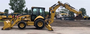
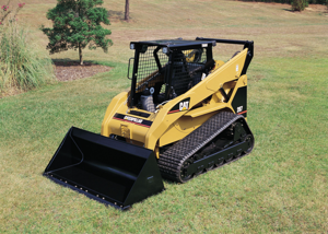
Explore Other Assets


© 2026 MaintainX. All rights reserved.