


Caterpillar Forklift DP35N
Need answers fast?
Explore the manual using AI.
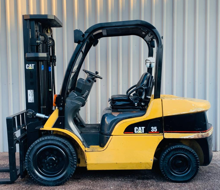
The Caterpillar Forklift DP35N is a robust industrial forklift designed for heavy-duty applications. Known for its reliability and efficiency, this model excels in material handling tasks, making it an essential asset for warehouses and construction sites. With advanced features and durable construction, it ensures optimal performance in demanding environments.
Turn manuals into instant answers
with your AI-powered assistantTurn manuals into instant answers
with your AI-powered assistant
Manual for Caterpillar Forklift DP35N
Complete asset maintenance, one click away
Get instant access to all the maintenance information you need. Empower technicians to perform preventive maintenance with asset packages, ready to use right out of the box.

Documents & Manuals
Find all the essential guides in one place.
 Tensioning Guide
- Belt-diagram
- C-120 pulleys
+ 13 more

Work Order Templates
Pre-built workflows to keep your asset running smoothly.
- Daily Electrical System Inspection
- Replace Roller and Pulley
- Install Engine B-120
+ 29 more

Procedures
Integrate maintenance plans directly into your work orders.
- Motion Industries
- Applied Industrial Technologies
- Electrical Brothers
+ 5 more

Parts
Access the parts list for your equipment in MaintainX.
- Drive Motor
- B2 Rollers
- Tensioning System
+ 40 more
Caterpillar Forklift DP35N
Create an account to install this asset package.
Maintenance Plans for Caterpillar Forklift Model DP35N
Integrate maintenance plans directly into your work orders in MaintainX.
Powershift Transmission Maintenance
Oil Pressure Measurement
(1) Transmission oil level check
(a) Check the transmission fluid level with the level gauge.
(b) Start and run the engine at an idling speed for about 3 minutes, and then stop the engine.
(c) Wait for about 30 seconds after stopping the engine, and check the level.
(d) The checking procedure must be completed within 5 minutes after the engine has stopped.
(2) Engine warm-up
(a) Warm up the engine to raise the temperature of the transmission oil.
(3) Engine speed measurement

Glow Relay Inspection
Inspection of coil
Apply a tester to terminal 3 and terminal 4 and measure the resistance value of the relay coil. Replace the coil with a new one if there is no continuity or the measured resistance value is outside the standard resistance value.
Inspection of contact
1. Measure the insulation resistance value between terminal 1 and terminal 2. Replace the contact with a new one if the measured insulation resistance value is not more than the value listed in the table below.
2. Apply a tester to terminal 1 and terminal 2.
3. When applying a voltage of 12 V ON and OFF across terminal 3 and terminal 4 under the above condition, check to see if the relay activates to cause continuity or not between terminal 1 and terminal 2. Replace the relay with a new one if it does not activate properly;
Fan Belt Maintenance
Fan Belt Inspection
(1) Check the belt for contamination with oil, grease and dust. Replace the belt if required. When the contamination is slight, remove it and clean with rag or wiping paper. Do not use gasoline, oil or any other solvent to clean the belt.
(2) During engine overhaul or belt tension adjustment, closely check the belt’s condition. Replace the belt with a new one if it has any sort of damage.
Fan Belt Tension
Apply a force of 98 N (10 kgf) [22 lbf] perpendicularly to the belt at a point midway between the fan pulley and tension pulley. Adjust the tension so that belt deflection becomes between 11 to 13 mm (0.43 to 0.51 in.).
Connecting Radiator Hoses
When connecting the hoses to the radiator, fit their ends fully on the fittings and secure them with clamps. Make sure that each hose is correctly connected and prevented from disconnection by the flare of the fitting.
Coolant
Fill the radiator with coolant containing antifreeze. Start and operate the engine to let it warm up while checking for abnormal noise. Make sure that the quantity of coolant is as specified by checking the level in the reserve tank.;
Brake System Maintenance
Automatic Adjuster Test
(1) With the clearance A between the lining and drum set approximately to specification, pull the cable with spring with a finger as shown. The lever should turn the adjusting screw wheel by one notch and, when the cable is released, return to the original position.
(2) If the lever fails, or is slow, to turn the adjusting screw wheel, check the position of the lever relative to the toothed wheel. The lever’s actuating tip should touch the toothed wheel at approximately 7 to 9 mm (0.28 to 0.35 in.) below the centerline of the screw. If the lever contact is out of the range, the lever will not correctly engage with the toothed wheel, therefore failing or slow to turn the wheel.
(3) If the automatic adjuster fails to operate correctly, take the following actions.
(a) Ensure that the adjusting spring is correctly hooked to the primary shoe.
(b) Replace the fitting cable.
(c) Replace the lever.
(d) Replace the adjusting screw.
Manual Adjustment
Power Relay Inspection
Inspection of coil
Apply a tester to terminal 1 and terminal 2 and measure the resistance value of the relay coil. Replace the coil with a new one if there is no continuity or the resistance value measured is outside the standard resistance value.
Inspection of contact
1. Measure the insulation resistance value between terminal 3 and terminal 4. Replace the contact with a new one if the measured insulation resistance value is not more than the value listed in the table below.
2. Apply the tester to terminal 3 and terminal 4.
3. When applying a voltage of 12 V ON and OFF across terminal 1 and terminal 2 under the above condition, check to see if the relay activates to cause continuity or not between terminal 3 and terminal 4. Replace the relay with a new one if it does not activate properly.
CAUTION: This part operates on DC 12 V (Gasoline/Dieselengine truck) power supply.
CAUTION: As the relay has an integrated diode between terminals, be careful about the polarity when inspecting. Replace the relay with a new one if an impact is given to it or if it is dropped.;
Parts for Caterpillar Forklift DP35N
Access the parts list for your equipment in MaintainX.
Wrench Removal and installation of pulley (To be used with 91268 - 00200) for 1,2,3 ton class
91268 - 00100
Wrench Removal and installation of pulley for 1,2,3 ton class
91268 - 00200
Bolt Removal of pump body (FC) and shifter case (MC) for 1,2,3 ton class
91268 -05100
Socket wrench Removal and installation of rear wheel nut and weight bolt for 1,2,3 ton class
91268 - 00701
Puller seat Removal of front wheel hub for 1 class ton
64309 - 10601
Unlock efficiency
with MaintainX CoPilot
MaintainX CoPilot is your expert colleague, on call 24/7, helping your team find the answers they need to keep equipment running.
Reduce Unplanned Downtime
Ensure your team follows consistent procedures to minimize equipment failures and costly delays.
Maximize Asset Availability
Keep your assets running longer and more reliably, with standardized maintenance workflows from OEM manuals.
Lower Maintenance Costs
Turn any technician into an expert to streamline operations, maintain more assets, and reduce overall costs.
Thousands of companies manage their assets with MaintainX

'%3e%3cpath%20fill='url(%23b)'%20d='M66.008%2080.068c-5.084-.786-9.763-3.834-12.442-8.68a16.942%2016.942%200%200%201-1.87-5.18c1.096.19%202.203.476%203.298.87%206.525%202.333%2010.836%207.68%2011.014%2012.99ZM51.47%2061.576c.488-5.524%203.62-10.716%208.847-13.597a17.132%2017.132%200%200%201%2011.335-1.882c-.798%208.145-7.43%2014.848-16.038%2015.599-1.417.119-2.799.07-4.144-.12Zm28.564-11.478a17.513%2017.513%200%200%201%203.727%204.62c4.608%208.335%201.584%2018.813-6.75%2023.409a16.988%2016.988%200%200%201-4.359%201.679%2019.624%2019.624%200%200%201-3.977-12.776c.346-7.561%204.942-13.931%2011.36-16.932Z'/%3e%3cpath%20fill='%23110F0D'%20fill-rule='evenodd'%20d='M142.831%2048.324h4.977V77.03h-4.977V48.324Zm27.278%2013.002c.322%201.048.453%202.263.453%203.62v12.073h-4.787V66.208c0-.75-.047-1.572-.154-2.143-.453-2.382-1.822-3.572-4.215-3.572-2.31%200-3.882%201.274-4.43%203.476-.143.596-.226%201.405-.226%202.25v10.8h-4.787V56.623h4.477v2.989c1.536-2.5%203.906-3.43%206.371-3.43%203.488%200%206.263%201.68%207.298%205.144Zm24.636%207.323c0%203.882-2.358%206.525-5.763%207.727-1.298.453-2.632.643-4.62.643h-10.169V48.324h9.085c1.691%200%203.156.143%204.049.38%203.465.93%205.727%203.68%205.727%207.335%200%202.441-.81%204.156-2.762%205.644%202.905%201.417%204.453%203.727%204.453%206.966Zm-15.634-8.656h4.584c1.024%200%201.917-.143%202.536-.417%201.215-.548%201.905-1.608%201.905-3.167%200-1.548-.643-2.572-1.845-3.132-.691-.31-1.762-.452-2.763-.452h-4.417v7.168Zm10.716%208.465c0-1.536-.893-3.37-3.227-3.893-.428-.095-1.036-.143-1.571-.143h-5.918v8.085h5.501c.56%200%201.429-.048%201.953-.167%201.94-.453%203.262-1.846%203.262-3.882Zm47.747-11.847-8.097%2020.408h-4.429l-8.109-20.408h5.191l5.192%2014.574%205.108-14.574h5.144Zm-20.218%2010.002c0%20.69-.036%201.262-.155%201.94h-15.943c.631%202.87%202.714%204.728%205.882%204.728%202.131%200%203.607-.882%204.703-2.525h4.87c-1.762%204.144-5.204%206.692-9.657%206.692-6.084%200-10.537-4.858-10.537-10.49%200-6.108%204.524-10.776%2010.335-10.776%206.239%200%2010.442%204.954%2010.502%2010.43Zm-4.763-1.405c-.333-2.846-2.643-4.858-5.691-4.858-2.894%200-5.287%201.929-5.621%204.858h11.312Zm-72.667%203.44c0%204.787-3.287%208.371-9.419%208.371H119.363V64.66c-1.917.274-3.87.69-5.811%201.238l4.537%2011.121h-5.418l-3.596-9.585c-5.144%202.084-10.085%205.216-14.217%209.585h-4.786L101.8%2048.312h4.56l5.68%2013.883a44.112%2044.112%200%200%201%207.323-1.774V48.312h9.084c1.703%200%203.156.143%204.061.393%203.453.929%205.727%203.667%205.727%207.323%200%201.917-.738%204.179-2.81%205.691%203.06%201.56%204.501%204.025%204.501%206.93Zm-15.634-8.667a62.664%2062.664%200%200%201%202.06-.036c1.703.012%203.239.131%204.608.37%201.441-.549%202.357-1.727%202.357-3.537%200-1.941-.881-3.144-2.488-3.667-.548-.18-1.358-.286-2.322-.286h-4.215v7.156Zm-16.55%203.905-3.715-9.894-6.394%2016.502c2.833-2.595%206.263-4.858%2010.109-6.608Zm27.254%204.74c0-2.775-3.131-4.347-8.513-4.418-.715%200-1.441.011-2.191.047v8.252h5.918c2.548%200%204.786-1.37%204.786-3.882Z'%20clip-rule='evenodd'/%3e%3c/g%3e%3cdefs%3e%3clinearGradient%20id='b'%20x1='51.47'%20x2='85.916'%20y1='62.946'%20y2='62.946'%20gradientUnits='userSpaceOnUse'%3e%3cstop%20stop-color='%23CD9F28'/%3e%3cstop%20offset='1'%20stop-color='%23ECD80B'/%3e%3c/linearGradient%3e%3cclipPath%20id='a'%3e%3cpath%20fill='%23fff'%20d='M51.47%2045.728h186.104V80.14H51.47z'/%3e%3c/clipPath%3e%3c/defs%3e%3c/svg%3e)


More from Caterpillar


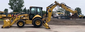
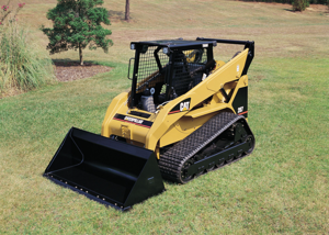
Explore Other Assets


© 2026 MaintainX. All rights reserved.