


'%3e%3cpath%20d='M10%2010.5V17h12.5v5.5l-21%20.038V15l8.5-4.5ZM1%206h11M6.5%202H12M5.5%2022.5V19'/%3e%3cpath%20d='M21.21%2017.012%2020.14%201.5h-4.28l-1.07%2015.512M15.516%206.49h4.967'/%3e%3c/g%3e%3cdefs%3e%3cclipPath%20id='a'%3e%3cpath%20fill='%23fff'%20d='M0%200h24v24H0z'/%3e%3c/clipPath%3e%3c/defs%3e%3c/svg%3e)











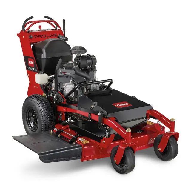
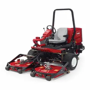
Toro Mower ProLine
Need answers fast?
Explore the manual using AI.
Turn manuals into instant answers
with your AI-powered assistantTurn manuals into instant answers
with your AI-powered assistant
Manual for Toro Mower ProLine
Complete asset maintenance, one click away
Get instant access to all the maintenance information you need. Empower technicians to perform preventive maintenance with asset packages, ready to use right out of the box.

Documents & Manuals
Find all the essential guides in one place.
 Tensioning Guide
- Belt-diagram
- C-120 pulleys
+ 13 more

Work Order Templates
Pre-built workflows to keep your asset running smoothly.
- Daily Electrical System Inspection
- Replace Roller and Pulley
- Install Engine B-120
+ 29 more

Procedures
Integrate maintenance plans directly into your work orders.
- Motion Industries
- Applied Industrial Technologies
- Electrical Brothers
+ 5 more

Parts
Access the parts list for your equipment in MaintainX.
- Drive Motor
- B2 Rollers
- Tensioning System
+ 40 more
Toro Mower ProLine
Create an account to install this asset package.
Maintenance Plans for Toro Mower Model ProLine
Integrate maintenance plans directly into your work orders in MaintainX.
8 Hourly Blade Spindle Bearings Lubrication
Warning: Stop the engine, remove the key and disconnect the spark plug wire(s) from the spark plug(s).
Engine stopped and spark plug wire(s) disconnected?
Upload a photo of the spindle bearings before lubrication
Spindle bearings greased through the holes in the mower deck cover?
Upload a photo of the spindle bearings after lubrication
Carrier frame mounting tubes and castor wheels greased?
Sign off on the blade spindle bearings lubrication

Blade Maintenance
Warning: A blade that is worn or damaged could break apart and pieces could be thrown at bystanders or at you as you use the mower.
Check the cutter blades daily for sharpness, and for any wear or damage.
Upload a photo of the blade if any nicks are found
If a blade is damaged or worn, replace it immediately with a genuine TORO replacement blade.
Before Inspecting or Servicing the Blades: Park the machine on a level surface, disengage the blade control (PTO) and set the parking brake. Turn the ignition key to “OFF” to stop the engine. Remove the key and disconnect the spark plug wire(s) from the spark plug(s).
Inspect the cutting edges. If the edges are not sharp or have nicks, remove and sharpen the blades.
Inspect the blades, especially the curved area. If you notice any damage, wear, or a slot forming in this area, immediately install a new blade.
Check for Bent Blades: Rotate the blades until the ends face forward and backward. Measure from a level surface to the cutting edge of the blades. Note this dimension.
Rotate the opposite ends of the blades forward. Measure from a level surface to the cutting edge of the blades at the same position as in step 1 above. The difference between the dimensions obtained in steps 1 and 2 must not exceed 1/8” (3 mm). If this dimension exceeds 1/8” (3 mm), the blade is bent and must be replaced.
Castor Wheel Fork Bushings Replacement
Warning: This procedure requires trained personnel with PPE!
Check if the castor fork is loose
If the castor fork is not loose, no need to replace the bushings
Raise the cutting unit and block up the front of the mower with jack stands
Remove the retaining ring and thrust washer(s) from the top of the castor wheel fork
Pull the castor wheel fork out of the mounting tube
Drive out the bushings and clean the inside of the mounting tube
Grease and drive the new bushings into the mounting tube
Inspect the castor wheel fork for wear and replace if necessary
Castor Wheels And Bearings Maintenance
Warning: This maintenance check requires trained personnel with PPE!
Remove the locknut and wheel bolt holding the castor wheel to the castor fork.
Remove the washer and bushing, then pull the spanner bushing and roller bearing out of the wheel hub.
Remove the other bushing from the wheel hub and clean any grease and dirt from the wheel hub.
Inspect the roller bearing, bushings, spanner bushing and inside of the wheel hub for wear. Replace any defective or worn parts.
To assemble, place one (1) bushing into the wheel hub. Grease the roller bearing and spanner bushing and slide them into the wheel hub. Place the second bushing into the wheel hub.
Install the castor wheel into the castor fork and secure with the wheel bolt and locknut. Tighten the locknut until the spanner bushing bottoms against the inside of the castor forks.
Grease the fitting on the castor wheel.
Sign off on the castor wheels and bearings maintenance
Cutting Unit Maintenance
If one cutter blade cuts lower than the other, correct as follows:
1. Stop the engine, remove the key and disconnect the spark plug wire(s) from the spark plug(s).
2. Adjust the tire pressure in all tires to specifications and check that the blades are not bent.
3. Set the height-of-cut to the 2-1/2” (64 mm) position. Refer to Adjusting the Height-Of-Cut in the Operation section. Make sure the clevis pins are resting on the frame cushions.
4. Rotate the blades so the tips line up with one another. The tips of both blades must be within 1/8” (3 mm) of each other. If the blade tips are not within 1/8” (3 mm) of each other, add shim washers (Part No. 3256-24) between the appropriate spindle housing and the bottom of the cutting unit to align the blades.
Setting the Front-to-Rear Pitch
1. Check the tire pressure.
2. Position the blades front-to-rear. Measure at “C” and “D” locations from a level surface to the cutting edge of the blades.
3. The mower should be 1/8”–5/8” (3–16 mm) lower in front “C” than in the rear “D”.
Unlock
efficiency with MaintainX Assist
MaintainX Assist is your expert colleague, on call 24/7, helping your team find the answers they need to keep equipment running.
'/%3e%3cpath%20d='M32.0001%2048.6663C22.7953%2048.6663%2015.3335%2041.2043%2015.3335%2031.9997C15.3335%2022.7949%2022.7954%2015.333%2032.0001%2015.333C39.463%2015.333%2045.7096%2020.2378%2047.8335%2026.9997H43.6668'%20stroke='white'%20stroke-width='2.85714'%20stroke-linecap='round'%20stroke-linejoin='round'/%3e%3cpath%20d='M32%2025.333V31.9997L35.3333%2035.333'%20stroke='white'%20stroke-width='2.85714'%20stroke-linecap='round'%20stroke-linejoin='round'/%3e%3cpath%20d='M48.5918%2033.6667C48.6413%2033.1182%2048.6667%2032.5622%2048.6667%2032M37%2048.6667C37.5693%2048.4793%2038.1255%2048.2607%2038.6667%2048.013M46.651%2040.3333C46.9725%2039.714%2047.2592%2039.0722%2047.5083%2038.4103M42.3208%2045.7153C42.8948%2045.2402%2043.4385%2044.7263%2043.948%2044.1775'%20stroke='white'%20stroke-width='2.85714'%20stroke-linecap='round'%20stroke-linejoin='round'/%3e%3cdefs%3e%3clinearGradient%20id='paint0_linear_9036_2820'%20x1='17.4188'%20y1='24.2718'%20x2='46.9529'%20y2='57.2957'%20gradientUnits='userSpaceOnUse'%3e%3cstop%20stop-color='%23246CFF'/%3e%3cstop%20offset='1'%20stop-color='%2321C779'/%3e%3c/linearGradient%3e%3c/defs%3e%3c/svg%3e)
Reduce Unplanned Downtime
Ensure your team follows consistent procedures to minimize equipment failures and costly delays.
'/%3e%3cpath%20d='M15.7599%2038.0533C15.8165%2037.5147%2016.2068%2037.0805%2016.9875%2036.2123L18.706%2034.2912C19.126%2033.7593%2019.4241%2032.833%2019.4241%2031.9993C19.4241%2031.1663%2019.1259%2030.2397%2018.7059%2029.708L16.9875%2027.7869C16.2068%2026.9186%2015.8164%2026.4845%2015.7599%2025.9458C15.7033%2025.4071%2015.9949%2024.9011%2016.578%2023.889L17.4007%2022.4613C18.0228%2021.3816%2018.3339%2020.8417%2018.8632%2020.6265C19.3925%2020.4112%2019.9911%2020.5811%2021.1883%2020.9208L23.2221%2021.4936C23.9864%2021.6699%2024.7883%2021.5699%2025.4862%2021.2113L26.0477%2020.8874C26.6462%2020.504%2027.1065%2019.9389%2027.3613%2019.2746L27.9179%2017.6122C28.2839%2016.5122%2028.4668%2015.9622%2028.9024%2015.6476C29.3381%2015.333%2029.9167%2015.333%2031.0739%2015.333H32.9319C34.0892%2015.333%2034.6679%2015.333%2035.1034%2015.6476C35.5391%2015.9622%2035.7221%2016.5122%2036.0881%2017.6122L36.6446%2019.2746C36.8994%2019.9389%2037.3597%2020.504%2037.9582%2020.8874L38.5197%2021.2113C39.2176%2021.5699%2040.0196%2021.6699%2040.7839%2021.4936L42.8176%2020.9208C44.0147%2020.5811%2044.6134%2020.4112%2045.1427%2020.6265C45.6721%2020.8417%2045.9831%2021.3816%2046.6052%2022.4613L47.4279%2023.889C48.0111%2024.9011%2048.3026%2025.4071%2048.2461%2025.9458C48.1894%2026.4845%2047.7991%2026.9186%2047.0184%2027.7869L45.2999%2029.708C44.8801%2030.2397%2044.5817%2031.1663%2044.5817%2031.9993C44.5817%2032.833%2044.8799%2033.7593%2045.2999%2034.2912L47.0184%2036.2123C47.7991%2037.0805%2048.1894%2037.5147%2048.2461%2038.0533C48.3026%2038.5922%2048.0111%2039.0982%2047.4279%2040.1102L46.6052%2041.5378C45.9831%2042.6175%2045.6721%2043.1575%2045.1427%2043.3727C44.6134%2043.588%2044.0147%2043.4182%2042.8176%2043.0783L40.7839%2042.5055C40.0194%2042.3292%2039.2174%2042.4293%2038.5194%2042.788L37.9581%2043.112C37.3596%2043.4953%2036.8994%2044.0603%2036.6447%2044.7247L36.0881%2046.3872C35.7221%2047.4872%2035.5391%2048.0372%2035.1034%2048.3517C34.6679%2048.6663%2034.0892%2048.6663%2032.9319%2048.6663H31.0739C29.9167%2048.6663%2029.3381%2048.6663%2028.9024%2048.3517C28.4668%2048.0372%2028.2839%2047.4872%2027.9179%2046.3872'%20stroke='white'%20stroke-width='2.85714'%20stroke-linecap='round'/%3e%3cpath%20d='M16.5614%2043.2993C18.3614%2041.4993%2024.4814%2035.4393%2025.0814%2034.7393C25.7157%2033.9993%2025.2014%2032.9993%2025.5074%2029.8993C25.6555%2028.3993%2025.9781%2027.2756%2026.9014%2026.4393C28.0014%2025.3993%2028.9015%2025.3993%2032.0015%2025.3294C34.7015%2025.3993%2035.0215%2025.0993%2035.3015%2025.7994C35.5015%2026.2994%2034.9015%2026.5993%2034.1815%2027.3994C32.5815%2028.9993%2031.6415%2029.7993%2031.5515%2030.2993C30.9015%2032.4993%2033.4615%2033.7993%2034.8615%2032.3993C35.3908%2031.8698%2037.8415%2029.3993%2038.0815%2029.1993C38.2615%2029.0393%2038.6923%2029.047%2038.9015%2029.2993C39.0815%2029.4762%2039.1015%2029.4993%2039.0815%2030.2993C39.063%2031.0398%2039.0712%2032.103%2039.0735%2033.1993C39.0763%2034.6198%2039.0015%2036.1993%2038.4015%2036.9993C37.2015%2038.7993%2035.2015%2038.8993%2033.4015%2038.9793C31.7015%2039.0793%2030.3015%2038.8993%2029.8615%2039.2193C29.5015%2039.3993%2027.6014%2041.3993%2025.3014%2043.6993L21.2014%2047.7993C17.8014%2050.4993%2014.0614%2046.2993%2016.5614%2043.2993Z'%20stroke='white'%20stroke-width='2.85714'%20stroke-linecap='round'/%3e%3cdefs%3e%3clinearGradient%20id='paint0_linear_9036_2840'%20x1='17.4188'%20y1='24.2718'%20x2='46.9529'%20y2='57.2957'%20gradientUnits='userSpaceOnUse'%3e%3cstop%20stop-color='%23246CFF'/%3e%3cstop%20offset='1'%20stop-color='%2321C779'/%3e%3c/linearGradient%3e%3c/defs%3e%3c/svg%3e)
Maximize Asset Availability
Keep your assets running longer and more reliably, with standardized maintenance workflows from OEM manuals.
'/%3e%3cpath%20d='M35.3333%2041.9997C42.6972%2041.9997%2048.6667%2036.0302%2048.6667%2028.6663C48.6667%2021.3025%2042.6972%2015.333%2035.3333%2015.333C27.9695%2015.333%2022%2021.3025%2022%2028.6663C22%2036.0302%2027.9695%2041.9997%2035.3333%2041.9997Z'%20stroke='white'%20stroke-width='2.85714'%20stroke-linecap='round'/%3e%3cpath%20d='M17.2611%2030.333C16.0422%2032.1957%2015.3335%2034.4222%2015.3335%2036.8143C15.3335%2043.36%2020.6398%2048.6663%2027.1854%2048.6663C29.5777%2048.6663%2031.8042%2047.9577%2033.6668%2046.7387'%20stroke='white'%20stroke-width='2.85714'%20stroke-linecap='round'/%3e%3cpath%20d='M38.2854%2025.6752C37.9251%2024.155%2036.0911%2022.7832%2033.8896%2023.8095C31.6881%2024.8357%2031.3384%2028.1376%2034.6684%2028.4884C36.1736%2028.647%2037.1548%2028.3044%2038.0533%2029.2733C38.9516%2030.2422%2039.1186%2032.9365%2036.8219%2033.6627C34.5253%2034.3888%2032.2511%2033.2542%2032.0034%2031.6432M35.3104%2022.0068V23.4552M35.3104%2033.8862V35.3402'%20stroke='white'%20stroke-width='2.85714'%20stroke-linecap='round'%20stroke-linejoin='round'/%3e%3cdefs%3e%3clinearGradient%20id='paint0_linear_9036_2830'%20x1='17.4188'%20y1='24.2718'%20x2='46.9529'%20y2='57.2957'%20gradientUnits='userSpaceOnUse'%3e%3cstop%20stop-color='%23246CFF'/%3e%3cstop%20offset='1'%20stop-color='%2321C779'/%3e%3c/linearGradient%3e%3c/defs%3e%3c/svg%3e)
Lower Maintenance Costs
Turn any technician into an expert to streamline operations, maintain more assets, and reduce overall costs.
Thousands of companies manage their assets with MaintainX

'%3e%3cpath%20fill='url(%23b)'%20d='M66.008%2080.068c-5.084-.786-9.763-3.834-12.442-8.68a16.942%2016.942%200%200%201-1.87-5.18c1.096.19%202.203.476%203.298.87%206.525%202.333%2010.836%207.68%2011.014%2012.99ZM51.47%2061.576c.488-5.524%203.62-10.716%208.847-13.597a17.132%2017.132%200%200%201%2011.335-1.882c-.798%208.145-7.43%2014.848-16.038%2015.599-1.417.119-2.799.07-4.144-.12Zm28.564-11.478a17.513%2017.513%200%200%201%203.727%204.62c4.608%208.335%201.584%2018.813-6.75%2023.409a16.988%2016.988%200%200%201-4.359%201.679%2019.624%2019.624%200%200%201-3.977-12.776c.346-7.561%204.942-13.931%2011.36-16.932Z'/%3e%3cpath%20fill='%23110F0D'%20fill-rule='evenodd'%20d='M142.831%2048.324h4.977V77.03h-4.977V48.324Zm27.278%2013.002c.322%201.048.453%202.263.453%203.62v12.073h-4.787V66.208c0-.75-.047-1.572-.154-2.143-.453-2.382-1.822-3.572-4.215-3.572-2.31%200-3.882%201.274-4.43%203.476-.143.596-.226%201.405-.226%202.25v10.8h-4.787V56.623h4.477v2.989c1.536-2.5%203.906-3.43%206.371-3.43%203.488%200%206.263%201.68%207.298%205.144Zm24.636%207.323c0%203.882-2.358%206.525-5.763%207.727-1.298.453-2.632.643-4.62.643h-10.169V48.324h9.085c1.691%200%203.156.143%204.049.38%203.465.93%205.727%203.68%205.727%207.335%200%202.441-.81%204.156-2.762%205.644%202.905%201.417%204.453%203.727%204.453%206.966Zm-15.634-8.656h4.584c1.024%200%201.917-.143%202.536-.417%201.215-.548%201.905-1.608%201.905-3.167%200-1.548-.643-2.572-1.845-3.132-.691-.31-1.762-.452-2.763-.452h-4.417v7.168Zm10.716%208.465c0-1.536-.893-3.37-3.227-3.893-.428-.095-1.036-.143-1.571-.143h-5.918v8.085h5.501c.56%200%201.429-.048%201.953-.167%201.94-.453%203.262-1.846%203.262-3.882Zm47.747-11.847-8.097%2020.408h-4.429l-8.109-20.408h5.191l5.192%2014.574%205.108-14.574h5.144Zm-20.218%2010.002c0%20.69-.036%201.262-.155%201.94h-15.943c.631%202.87%202.714%204.728%205.882%204.728%202.131%200%203.607-.882%204.703-2.525h4.87c-1.762%204.144-5.204%206.692-9.657%206.692-6.084%200-10.537-4.858-10.537-10.49%200-6.108%204.524-10.776%2010.335-10.776%206.239%200%2010.442%204.954%2010.502%2010.43Zm-4.763-1.405c-.333-2.846-2.643-4.858-5.691-4.858-2.894%200-5.287%201.929-5.621%204.858h11.312Zm-72.667%203.44c0%204.787-3.287%208.371-9.419%208.371H119.363V64.66c-1.917.274-3.87.69-5.811%201.238l4.537%2011.121h-5.418l-3.596-9.585c-5.144%202.084-10.085%205.216-14.217%209.585h-4.786L101.8%2048.312h4.56l5.68%2013.883a44.112%2044.112%200%200%201%207.323-1.774V48.312h9.084c1.703%200%203.156.143%204.061.393%203.453.929%205.727%203.667%205.727%207.323%200%201.917-.738%204.179-2.81%205.691%203.06%201.56%204.501%204.025%204.501%206.93Zm-15.634-8.667a62.664%2062.664%200%200%201%202.06-.036c1.703.012%203.239.131%204.608.37%201.441-.549%202.357-1.727%202.357-3.537%200-1.941-.881-3.144-2.488-3.667-.548-.18-1.358-.286-2.322-.286h-4.215v7.156Zm-16.55%203.905-3.715-9.894-6.394%2016.502c2.833-2.595%206.263-4.858%2010.109-6.608Zm27.254%204.74c0-2.775-3.131-4.347-8.513-4.418-.715%200-1.441.011-2.191.047v8.252h5.918c2.548%200%204.786-1.37%204.786-3.882Z'%20clip-rule='evenodd'/%3e%3c/g%3e%3cdefs%3e%3clinearGradient%20id='b'%20x1='51.47'%20x2='85.916'%20y1='62.946'%20y2='62.946'%20gradientUnits='userSpaceOnUse'%3e%3cstop%20stop-color='%23CD9F28'/%3e%3cstop%20offset='1'%20stop-color='%23ECD80B'/%3e%3c/linearGradient%3e%3cclipPath%20id='a'%3e%3cpath%20fill='%23fff'%20d='M51.47%2045.728h186.104V80.14H51.47z'/%3e%3c/clipPath%3e%3c/defs%3e%3c/svg%3e)











More from Toro
Explore Other Assets





© 2026 MaintainX. All rights reserved.