


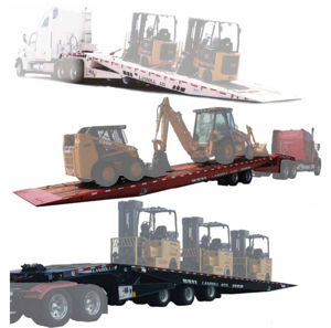
Landoll Axle Trailer 455-48'
Need answers fast?
Explore the manual using AI.

Turn manuals into instant answers
with your AI-powered assistantTurn manuals into instant answers
with your AI-powered assistant
Manual for Landoll Axle Trailer 455-48'
Complete asset maintenance, one click away
Get instant access to all the maintenance information you need. Empower technicians to perform preventive maintenance with asset packages, ready to use right out of the box.

Documents & Manuals
Find all the essential guides in one place.
 Tensioning Guide
- Belt-diagram
- C-120 pulleys
+ 13 more

Work Order Templates
Pre-built workflows to keep your asset running smoothly.
- Daily Electrical System Inspection
- Replace Roller and Pulley
- Install Engine B-120
+ 29 more

Procedures
Integrate maintenance plans directly into your work orders.
- Motion Industries
- Applied Industrial Technologies
- Electrical Brothers
+ 5 more

Parts
Access the parts list for your equipment in MaintainX.
- Drive Motor
- B2 Rollers
- Tensioning System
+ 40 more
Landoll Axle Trailer 455-48'
Create an account to install this asset package.
Maintenance Plans for Landoll Axle Trailer Model 455-48'
Integrate maintenance plans directly into your work orders in MaintainX.
Hub / Drum Maintenance
WARNING: Failure to replace faulty brake drums will result in an unreliable braking system, and may lead to an accident.
1. Clean and inspect the brake drums whenever relining the brakes. To be suitable for further service, the brake drum should pass the following checks.
a. The brake surface should be free of scoring, excessive heat checks and cracks.
b. The brake surface diameter should be within the maximum diameter cast or stamped on the drum.
c. The mounting holes and pilot must be round and true.
d. The mounting surface must be clean and flat.
2. It may be necessary to turn or resurface the braking surface to remove small heat checks or other surface defects resulting from normal use.
a. The maximum diameter cast into the back plate portion of the brake drum is the maximum diameter or discard diameter to which the brake drum may be turned or worn and still be usable. If any portion of the brake surface exceeds the maximum diameter it must be discarded. The maximum is .120 over the nominal new diameter unless stated otherwise on the casting. The maximum diameter cast into the brake drum supersedes all published information.
b. When resurfacing a drum, allow at least 0.040 inches under the maximum diameter for additional wear.

Caging the Power Spring Removal
Chock all tractor and trailer wheels and drain the air system
Mark the brake chamber for proper air line port alignment for reassembly
CAGE THE POWER SPRING following the steps outlined in “Caging the Power Spring” on page 4-19
Disconnect the slack adjuster from the connecting rod by removing the clevis pin
Mark all air service lines for proper reinstallation and disconnect from the brake chamber
Remove the brake chamber from the axle brackets
Triple Axle Air Ride Height Adjustment
Before adjusting, the vehicle must be empty with the kingpin at operating height and have air supplied to the trailer.
Disconnect linkage at all three control arms and raise the center axle control arm to the “up” position
Raise the trailer until a spacer block can be placed between axle tube and undercarriage frame
Lower the trailer by exhausting air from the air springs by moving the control arm to the “down” position until the axle tube is resting on the block
Return the control arms slowly to the center position
Insert wood locating pins into the adjusting block and bracket on the height control valves
Loosen the 1/4” adjusting lock nuts located on the adjusting blocks
Reconnect the linkages and torque to 24-48 inch lbs
Retighten the 1/4” adjusting lock nuts at the adjusting blocks to 24-48 in. lbs
Slack Adjuster Adjustment
Rotate the manual adjuster clockwise until brake shoes contact drum
Back off manual adjuster 1/2 turn (counterclockwise)
Manually uncage the spring brake
Build up vehicle air pressure
Fully apply and release the brakes several times to check for adequate clearance to all adjacent components
Measure the distance from air chamber to 1/2” pin
Apply brakes with 100-105 psi air pressure and remeasure distance to 1/2” pins
Calculate the stroke (difference of these two measurements)
The stroke (difference of these two measurements) must be less than 2 inches
Tandem Axle Air Ride Height Adjustment
Vehicle is empty with the kingpin at operating height and have air supplied to the trailer
Linkage at the control arm disconnected and control arm raised to the “up” position
Block placed between axle tube and undercarriage frame
Wood block positioned between the axle tube and frame according to table
Trailer lowered by exhausting air from the air springs by moving the control arm to the “down” position until the axle tube is resting on the block
Ride height checked and is correct
1/4” adjusting lock nut located on the adjusting block loosened, allowing the control arm to move approximately 1 inch
Adjusting block moved until holes align, then locating pin inserted
Control arm linkage aligned to the control arm lower bracket and 1/4” adjusting lock nut re-tightened to 2-4 ft. lbs
Unlock efficiency
with MaintainX CoPilot
MaintainX CoPilot is your expert colleague, on call 24/7, helping your team find the answers they need to keep equipment running.
Reduce Unplanned Downtime
Ensure your team follows consistent procedures to minimize equipment failures and costly delays.
Maximize Asset Availability
Keep your assets running longer and more reliably, with standardized maintenance workflows from OEM manuals.
Lower Maintenance Costs
Turn any technician into an expert to streamline operations, maintain more assets, and reduce overall costs.
Thousands of companies manage their assets with MaintainX

'%3e%3cpath%20fill='url(%23b)'%20d='M66.008%2080.068c-5.084-.786-9.763-3.834-12.442-8.68a16.942%2016.942%200%200%201-1.87-5.18c1.096.19%202.203.476%203.298.87%206.525%202.333%2010.836%207.68%2011.014%2012.99ZM51.47%2061.576c.488-5.524%203.62-10.716%208.847-13.597a17.132%2017.132%200%200%201%2011.335-1.882c-.798%208.145-7.43%2014.848-16.038%2015.599-1.417.119-2.799.07-4.144-.12Zm28.564-11.478a17.513%2017.513%200%200%201%203.727%204.62c4.608%208.335%201.584%2018.813-6.75%2023.409a16.988%2016.988%200%200%201-4.359%201.679%2019.624%2019.624%200%200%201-3.977-12.776c.346-7.561%204.942-13.931%2011.36-16.932Z'/%3e%3cpath%20fill='%23110F0D'%20fill-rule='evenodd'%20d='M142.831%2048.324h4.977V77.03h-4.977V48.324Zm27.278%2013.002c.322%201.048.453%202.263.453%203.62v12.073h-4.787V66.208c0-.75-.047-1.572-.154-2.143-.453-2.382-1.822-3.572-4.215-3.572-2.31%200-3.882%201.274-4.43%203.476-.143.596-.226%201.405-.226%202.25v10.8h-4.787V56.623h4.477v2.989c1.536-2.5%203.906-3.43%206.371-3.43%203.488%200%206.263%201.68%207.298%205.144Zm24.636%207.323c0%203.882-2.358%206.525-5.763%207.727-1.298.453-2.632.643-4.62.643h-10.169V48.324h9.085c1.691%200%203.156.143%204.049.38%203.465.93%205.727%203.68%205.727%207.335%200%202.441-.81%204.156-2.762%205.644%202.905%201.417%204.453%203.727%204.453%206.966Zm-15.634-8.656h4.584c1.024%200%201.917-.143%202.536-.417%201.215-.548%201.905-1.608%201.905-3.167%200-1.548-.643-2.572-1.845-3.132-.691-.31-1.762-.452-2.763-.452h-4.417v7.168Zm10.716%208.465c0-1.536-.893-3.37-3.227-3.893-.428-.095-1.036-.143-1.571-.143h-5.918v8.085h5.501c.56%200%201.429-.048%201.953-.167%201.94-.453%203.262-1.846%203.262-3.882Zm47.747-11.847-8.097%2020.408h-4.429l-8.109-20.408h5.191l5.192%2014.574%205.108-14.574h5.144Zm-20.218%2010.002c0%20.69-.036%201.262-.155%201.94h-15.943c.631%202.87%202.714%204.728%205.882%204.728%202.131%200%203.607-.882%204.703-2.525h4.87c-1.762%204.144-5.204%206.692-9.657%206.692-6.084%200-10.537-4.858-10.537-10.49%200-6.108%204.524-10.776%2010.335-10.776%206.239%200%2010.442%204.954%2010.502%2010.43Zm-4.763-1.405c-.333-2.846-2.643-4.858-5.691-4.858-2.894%200-5.287%201.929-5.621%204.858h11.312Zm-72.667%203.44c0%204.787-3.287%208.371-9.419%208.371H119.363V64.66c-1.917.274-3.87.69-5.811%201.238l4.537%2011.121h-5.418l-3.596-9.585c-5.144%202.084-10.085%205.216-14.217%209.585h-4.786L101.8%2048.312h4.56l5.68%2013.883a44.112%2044.112%200%200%201%207.323-1.774V48.312h9.084c1.703%200%203.156.143%204.061.393%203.453.929%205.727%203.667%205.727%207.323%200%201.917-.738%204.179-2.81%205.691%203.06%201.56%204.501%204.025%204.501%206.93Zm-15.634-8.667a62.664%2062.664%200%200%201%202.06-.036c1.703.012%203.239.131%204.608.37%201.441-.549%202.357-1.727%202.357-3.537%200-1.941-.881-3.144-2.488-3.667-.548-.18-1.358-.286-2.322-.286h-4.215v7.156Zm-16.55%203.905-3.715-9.894-6.394%2016.502c2.833-2.595%206.263-4.858%2010.109-6.608Zm27.254%204.74c0-2.775-3.131-4.347-8.513-4.418-.715%200-1.441.011-2.191.047v8.252h5.918c2.548%200%204.786-1.37%204.786-3.882Z'%20clip-rule='evenodd'/%3e%3c/g%3e%3cdefs%3e%3clinearGradient%20id='b'%20x1='51.47'%20x2='85.916'%20y1='62.946'%20y2='62.946'%20gradientUnits='userSpaceOnUse'%3e%3cstop%20stop-color='%23CD9F28'/%3e%3cstop%20offset='1'%20stop-color='%23ECD80B'/%3e%3c/linearGradient%3e%3cclipPath%20id='a'%3e%3cpath%20fill='%23fff'%20d='M51.47%2045.728h186.104V80.14H51.47z'/%3e%3c/clipPath%3e%3c/defs%3e%3c/svg%3e)


More from Landoll


Explore Other Assets


© 2026 MaintainX. All rights reserved.