


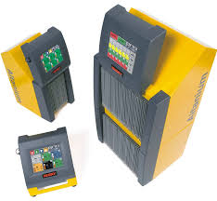
Husky Temperature Controller Altanium Neo2
Need answers fast?
Explore the manual using AI.
Turn manuals into instant answers
with your AI-powered assistantTurn manuals into instant answers
with your AI-powered assistant
Manual for Husky Temperature Controller Altanium Neo2
Complete asset maintenance, one click away
Get instant access to all the maintenance information you need. Empower technicians to perform preventive maintenance with asset packages, ready to use right out of the box.

Documents & Manuals
Find all the essential guides in one place.
 Tensioning Guide
- Belt-diagram
- C-120 pulleys
+ 13 more

Work Order Templates
Pre-built workflows to keep your asset running smoothly.
- Daily Electrical System Inspection
- Replace Roller and Pulley
- Install Engine B-120
+ 29 more

Procedures
Integrate maintenance plans directly into your work orders.
- Motion Industries
- Applied Industrial Technologies
- Electrical Brothers
+ 5 more

Parts
Access the parts list for your equipment in MaintainX.
- Drive Motor
- B2 Rollers
- Tensioning System
+ 40 more
Husky Temperature Controller Altanium Neo2
Create an account to install this asset package.
Maintenance Plans for Husky Temperature Controller Model Altanium Neo2
Integrate maintenance plans directly into your work orders in MaintainX.
Intelligent Control Card Replacement
WARNING!: Electrical and mechanical hazard- risk of death, serious injury and/or damage to the equipment. Turn off all power to the system and disconnect it completely from the main input power. Use a ground strap when handling any of the Altanium components.
Locate the Card Cage that contains the faulty ICC2 or ICC3. Use the on-screen Card Layout feature to assist in locating the card.
CAUTION!: Mechanical failure mode - attempting to remove a card when the upper and lower heatsink mounting screws are not fully disengaged from the female threads on the cabinet can result in catastrophic damage to the card.
Loosen the upper and lower slotted screws on the heat sink from the female threads in the cabinet.
Slide a screwdriver between the silver post and the ledge on the cabinet and gently pry the board out.
CAUTION! Static electricity hazard - risk of damage to the equipment. Do not, under any circumstances, place any PCB on carpets, rugs, or other material that is likely to create a static charge.
Carefully place the card on an earthed/grounded surface.
Slide the new card into to the slot and push the card slowly and firmly back into place. An incorrectly oriented card will not seat properly.
Tighten the upper and lower slotted screws on the heat sink.

Connections Check
Connect the thermocouple and power output cables (if required)
Resistance between the mold and the mold ground terminal on the system
Is the main input power disconnect in the OFF position prior to connection of the controller to the power source?
Sign off on the connections check
Intelligent Control Card Blown Fuse Replacement
DANGER! Hazardous voltage – risk of electrical shock or burns. The controller must be disconnected from the power source before maintenance is performed. Make sure the controller is turned off and unplugged. Lock out and tag the controller in accordance with local codes.
Make sure the work area is blocked off and a Danger sign is posted at all entry points. Always maintain control of the work area and the power plug.
Turn the main input power disconnect switch to the OFF position.
Disconnect the controller from the power source.
Attach a lock and tag to the main input power disconnect switch.
CAUTION! Static electricity hazard – risk of damage to equipment. Electronic devices could be severely damaged by static electricity.
Make sure you are properly grounded by either wearing an anti-static strap or touching a large grounded metal surface for several seconds.
Locate the Card Cage that contains the faulty ICC2 or ICC3 (Intelligent Control Card).
Loosen the upper and lower slotted screws on the heat sink.
Internal Cooling Fan and Display Blown Fuse Replacement
Warning: Mechanical hazard - risk of damage to the device. When replacing the fuses, take care not to stress the wire harnesses that run between the mainframe and the access panel.
Cooling fan stopped running?
Operator interface blank?
If both checks are 'FAIL', proceed with the following steps.
Removed the screws holding the upper access panel on the back of the controller mainframe?
Located the fuse block on the inside of the panel between the fan and the disconnect switch?
Enter the part number of the replacement fuse used
Replaced the fuses with SIBA part number 189020 6.3 Amp or equivalent only?
Installed the rear panel back and tightened the mounting screws without pinching the wires between the panel and the mainframe?
Display Replacement
Warning: Hazardous voltage – risk of electrical shock or burns. The controller must be disconnected from the power source before maintenance is performed. Make sure the controller is turned off and unplugged. Lock out and tag the controller in accordance with local codes.
Make sure the work area is blocked off and a Danger sign is posted at all entry points. Always maintain control of the work area and the power plug.
Turn the main input power disconnect switch to the OFF position.
Disconnect the controller from the power source.
Attach a lock and tag to the main input power disconnect switch.
Face the front of the system and rotate the display in the full forward position.
It is recommended that a second person provides assistance.
Using a 4 mm hex wrench, remove the two M5 screws that hold the Neo2 display to the mainframe.
Carefully pull the display away from the mainframe. This exposes the cable connectors between the mainframe and the display.
Parts for Husky Temperature Controller Altanium Neo2
Access the parts list for your equipment in MaintainX.
Fuse, 6.3 Amp
189020
Fuse, 6.3 Amp
189020
Fuse, 6.3 Amp
189020
Unlock efficiency
with MaintainX CoPilot
MaintainX CoPilot is your expert colleague, on call 24/7, helping your team find the answers they need to keep equipment running.
Reduce Unplanned Downtime
Ensure your team follows consistent procedures to minimize equipment failures and costly delays.
Maximize Asset Availability
Keep your assets running longer and more reliably, with standardized maintenance workflows from OEM manuals.
Lower Maintenance Costs
Turn any technician into an expert to streamline operations, maintain more assets, and reduce overall costs.
Thousands of companies manage their assets with MaintainX

'%3e%3cpath%20fill='url(%23b)'%20d='M66.008%2080.068c-5.084-.786-9.763-3.834-12.442-8.68a16.942%2016.942%200%200%201-1.87-5.18c1.096.19%202.203.476%203.298.87%206.525%202.333%2010.836%207.68%2011.014%2012.99ZM51.47%2061.576c.488-5.524%203.62-10.716%208.847-13.597a17.132%2017.132%200%200%201%2011.335-1.882c-.798%208.145-7.43%2014.848-16.038%2015.599-1.417.119-2.799.07-4.144-.12Zm28.564-11.478a17.513%2017.513%200%200%201%203.727%204.62c4.608%208.335%201.584%2018.813-6.75%2023.409a16.988%2016.988%200%200%201-4.359%201.679%2019.624%2019.624%200%200%201-3.977-12.776c.346-7.561%204.942-13.931%2011.36-16.932Z'/%3e%3cpath%20fill='%23110F0D'%20fill-rule='evenodd'%20d='M142.831%2048.324h4.977V77.03h-4.977V48.324Zm27.278%2013.002c.322%201.048.453%202.263.453%203.62v12.073h-4.787V66.208c0-.75-.047-1.572-.154-2.143-.453-2.382-1.822-3.572-4.215-3.572-2.31%200-3.882%201.274-4.43%203.476-.143.596-.226%201.405-.226%202.25v10.8h-4.787V56.623h4.477v2.989c1.536-2.5%203.906-3.43%206.371-3.43%203.488%200%206.263%201.68%207.298%205.144Zm24.636%207.323c0%203.882-2.358%206.525-5.763%207.727-1.298.453-2.632.643-4.62.643h-10.169V48.324h9.085c1.691%200%203.156.143%204.049.38%203.465.93%205.727%203.68%205.727%207.335%200%202.441-.81%204.156-2.762%205.644%202.905%201.417%204.453%203.727%204.453%206.966Zm-15.634-8.656h4.584c1.024%200%201.917-.143%202.536-.417%201.215-.548%201.905-1.608%201.905-3.167%200-1.548-.643-2.572-1.845-3.132-.691-.31-1.762-.452-2.763-.452h-4.417v7.168Zm10.716%208.465c0-1.536-.893-3.37-3.227-3.893-.428-.095-1.036-.143-1.571-.143h-5.918v8.085h5.501c.56%200%201.429-.048%201.953-.167%201.94-.453%203.262-1.846%203.262-3.882Zm47.747-11.847-8.097%2020.408h-4.429l-8.109-20.408h5.191l5.192%2014.574%205.108-14.574h5.144Zm-20.218%2010.002c0%20.69-.036%201.262-.155%201.94h-15.943c.631%202.87%202.714%204.728%205.882%204.728%202.131%200%203.607-.882%204.703-2.525h4.87c-1.762%204.144-5.204%206.692-9.657%206.692-6.084%200-10.537-4.858-10.537-10.49%200-6.108%204.524-10.776%2010.335-10.776%206.239%200%2010.442%204.954%2010.502%2010.43Zm-4.763-1.405c-.333-2.846-2.643-4.858-5.691-4.858-2.894%200-5.287%201.929-5.621%204.858h11.312Zm-72.667%203.44c0%204.787-3.287%208.371-9.419%208.371H119.363V64.66c-1.917.274-3.87.69-5.811%201.238l4.537%2011.121h-5.418l-3.596-9.585c-5.144%202.084-10.085%205.216-14.217%209.585h-4.786L101.8%2048.312h4.56l5.68%2013.883a44.112%2044.112%200%200%201%207.323-1.774V48.312h9.084c1.703%200%203.156.143%204.061.393%203.453.929%205.727%203.667%205.727%207.323%200%201.917-.738%204.179-2.81%205.691%203.06%201.56%204.501%204.025%204.501%206.93Zm-15.634-8.667a62.664%2062.664%200%200%201%202.06-.036c1.703.012%203.239.131%204.608.37%201.441-.549%202.357-1.727%202.357-3.537%200-1.941-.881-3.144-2.488-3.667-.548-.18-1.358-.286-2.322-.286h-4.215v7.156Zm-16.55%203.905-3.715-9.894-6.394%2016.502c2.833-2.595%206.263-4.858%2010.109-6.608Zm27.254%204.74c0-2.775-3.131-4.347-8.513-4.418-.715%200-1.441.011-2.191.047v8.252h5.918c2.548%200%204.786-1.37%204.786-3.882Z'%20clip-rule='evenodd'/%3e%3c/g%3e%3cdefs%3e%3clinearGradient%20id='b'%20x1='51.47'%20x2='85.916'%20y1='62.946'%20y2='62.946'%20gradientUnits='userSpaceOnUse'%3e%3cstop%20stop-color='%23CD9F28'/%3e%3cstop%20offset='1'%20stop-color='%23ECD80B'/%3e%3c/linearGradient%3e%3cclipPath%20id='a'%3e%3cpath%20fill='%23fff'%20d='M51.47%2045.728h186.104V80.14H51.47z'/%3e%3c/clipPath%3e%3c/defs%3e%3c/svg%3e)


More from Husky


Explore Other Assets


© 2026 MaintainX. All rights reserved.