


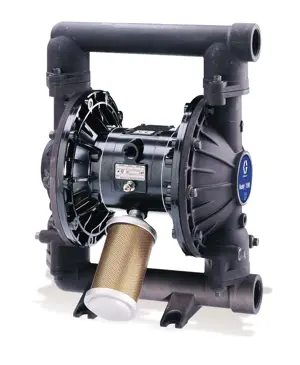
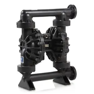
Husky Air-Operated Diaphragm Pump 205
Need answers fast?
Explore the manual using AI.
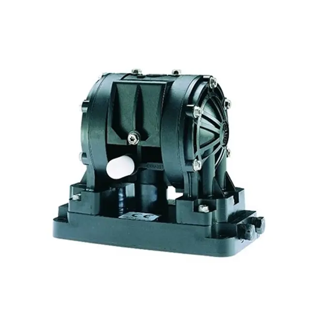
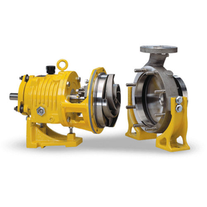
The Husky Air-Operated Diaphragm Pump 205 is a reliable and efficient pump designed for various industrial applications. Known for its durability and performance, this model ensures optimal fluid transfer with minimal maintenance requirements, making it an essential asset for any facility.
Turn manuals into instant answers
with your AI-powered assistantTurn manuals into instant answers
with your AI-powered assistant
Manual for Husky Air-Operated Diaphragm Pump 205
Complete asset maintenance, one click away
Get instant access to all the maintenance information you need. Empower technicians to perform preventive maintenance with asset packages, ready to use right out of the box.

Documents & Manuals
Find all the essential guides in one place.
 Tensioning Guide
- Belt-diagram
- C-120 pulleys
+ 13 more

Work Order Templates
Pre-built workflows to keep your asset running smoothly.
- Daily Electrical System Inspection
- Replace Roller and Pulley
- Install Engine B-120
+ 29 more

Procedures
Integrate maintenance plans directly into your work orders.
- Motion Industries
- Applied Industrial Technologies
- Electrical Brothers
+ 5 more

Parts
Access the parts list for your equipment in MaintainX.
- Drive Motor
- B2 Rollers
- Tensioning System
+ 40 more
Husky Air-Operated Diaphragm Pump 205
Create an account to install this asset package.
Maintenance Plans for Husky Air-Operated Diaphragm Pump Model 205
Integrate maintenance plans directly into your work orders in MaintainX.
Check Valves Replacement
WARNING: To reduce the risk of serious injury whenever you are instructed to relieve pressure, always follow the Pressure Relief Procedure
Shut off air and reserve air to the pump
Open the dispensing valve if the system has one
Open the fluid drain valve to relieve all system pressure, and have a container ready to catch the drainage
Remove the eight screws that hold the fluid cover/center housing assembly on the manifold, and lift the manifold covers/center housing assembly off of the manifold
Remove and replace the check valves, being careful to orient each check valve exactly like the one it is replacing. Make sure the check valve/seat area is clean
Remove and replace the sealing o-rings. Once compressed, o-rings may not be reused. Make sure the check valve/seat area is clean prior to fully seating o-rings into fluid cover grooves
Reinstall the fluid covers/center housing assembly on the manifold, install the screws that fasten the fluid covers/center housing assembly to the manifold, and torque to 42-47 in-lb (4.5-5.0 N•m). See Torque Sequence
Reconnect the pump

500 Hourly / 1 Monthly Diaphragm Pump Lubrication
CAUTION: Do not over-lubricate the pump. Excess oil is exhausted through the muffler, which could contaminate your fluid supply or other equipment.
The air valve is lubricated at the factory and designed to operate without additional lubrication.
Is the pump operating without additional lubrication?
If added lubrication is desired, every 500 hours of operation (or monthly), remove the hose from the pump air inlet and add two drops of machine oil to the air inlet.
Enter the number of hours of operation
Was the hose removed from the pump air inlet?
Were two drops of machine oil added to the air inlet?
Sign off on the pump lubrication
Diaphragm Replacement
Relieve the pressure, and disconnect the air line from the pump
Shut off air and reserve air to the pump
Open the dispensing valve if the system has one
Open the fluid drain valve to relieve all system pressure, and have a container ready to catch the drainage
Remove the eight screws that fasten the two fluid covers to manifold, and remove the fluid cover/center housing assembly from the manifold
Remove the six screws that fasten each fluid cover to the center housing, and pull the fluid covers off of the center housing
Remove the diaphragm plates from the shaft, and remove the diaphragms, and air-side diaphragm plates
Remove the diaphragm pins, remove and replace the o-rings, and reinstall the diaphragm pins in the center housing
Grease the length of the shaft, and slide it through the center housing
2 Monthly Threaded Connections Tightening
Check all hoses for wear or damage
Check all threaded connections are tight and free of leaks
Check fasteners
Tighten or retorque as necessary
Although pump use varies, a general guideline is to retorque fasteners every two months
Sign off on the threaded connections tightening
Air Valve Maintenance
WARNING: To reduce the risk of serious injury whenever you are instructed to relieve pressure, always follow the Pressure Relief Procedure
Shut off air and reserve air to the pump.
Open the dispensing valve if the system has one.
Open the fluid drain valve to relieve all system pressure, and have a container ready to catch the drainage.
Remove the four screws that hold the valve cover on the center housing.
Remove the valve block and valve carriage, and replace the u-cups.
Replace the valve carriage and valve block. When you replace the valve carriage, position it all the way to one side or the other.
NOTE: The valve block shown in FIG. 5 is for pumps with an air-operated air motor. If your pump has a solenoid-operated air motor, this step does not pertain.
Clean any parts that are dirty.
Parts for Husky Air-Operated Diaphragm Pump 205
Access the parts list for your equipment in MaintainX.
Carriage
191157
Housing
240898
Seal
113869
Plate
191141
Valve Block
194533
Carriage
191157
Housing
240898
Seal
113869
Plate
191141
Valve Block
194533
Carriage
191157
Housing
240898
Seal
113869
Plate
191141
Valve Block
194533
Unlock efficiency
with MaintainX CoPilot
MaintainX CoPilot is your expert colleague, on call 24/7, helping your team find the answers they need to keep equipment running.
Reduce Unplanned Downtime
Ensure your team follows consistent procedures to minimize equipment failures and costly delays.
Maximize Asset Availability
Keep your assets running longer and more reliably, with standardized maintenance workflows from OEM manuals.
Lower Maintenance Costs
Turn any technician into an expert to streamline operations, maintain more assets, and reduce overall costs.
Thousands of companies manage their assets with MaintainX

'%3e%3cpath%20fill='url(%23b)'%20d='M66.008%2080.068c-5.084-.786-9.763-3.834-12.442-8.68a16.942%2016.942%200%200%201-1.87-5.18c1.096.19%202.203.476%203.298.87%206.525%202.333%2010.836%207.68%2011.014%2012.99ZM51.47%2061.576c.488-5.524%203.62-10.716%208.847-13.597a17.132%2017.132%200%200%201%2011.335-1.882c-.798%208.145-7.43%2014.848-16.038%2015.599-1.417.119-2.799.07-4.144-.12Zm28.564-11.478a17.513%2017.513%200%200%201%203.727%204.62c4.608%208.335%201.584%2018.813-6.75%2023.409a16.988%2016.988%200%200%201-4.359%201.679%2019.624%2019.624%200%200%201-3.977-12.776c.346-7.561%204.942-13.931%2011.36-16.932Z'/%3e%3cpath%20fill='%23110F0D'%20fill-rule='evenodd'%20d='M142.831%2048.324h4.977V77.03h-4.977V48.324Zm27.278%2013.002c.322%201.048.453%202.263.453%203.62v12.073h-4.787V66.208c0-.75-.047-1.572-.154-2.143-.453-2.382-1.822-3.572-4.215-3.572-2.31%200-3.882%201.274-4.43%203.476-.143.596-.226%201.405-.226%202.25v10.8h-4.787V56.623h4.477v2.989c1.536-2.5%203.906-3.43%206.371-3.43%203.488%200%206.263%201.68%207.298%205.144Zm24.636%207.323c0%203.882-2.358%206.525-5.763%207.727-1.298.453-2.632.643-4.62.643h-10.169V48.324h9.085c1.691%200%203.156.143%204.049.38%203.465.93%205.727%203.68%205.727%207.335%200%202.441-.81%204.156-2.762%205.644%202.905%201.417%204.453%203.727%204.453%206.966Zm-15.634-8.656h4.584c1.024%200%201.917-.143%202.536-.417%201.215-.548%201.905-1.608%201.905-3.167%200-1.548-.643-2.572-1.845-3.132-.691-.31-1.762-.452-2.763-.452h-4.417v7.168Zm10.716%208.465c0-1.536-.893-3.37-3.227-3.893-.428-.095-1.036-.143-1.571-.143h-5.918v8.085h5.501c.56%200%201.429-.048%201.953-.167%201.94-.453%203.262-1.846%203.262-3.882Zm47.747-11.847-8.097%2020.408h-4.429l-8.109-20.408h5.191l5.192%2014.574%205.108-14.574h5.144Zm-20.218%2010.002c0%20.69-.036%201.262-.155%201.94h-15.943c.631%202.87%202.714%204.728%205.882%204.728%202.131%200%203.607-.882%204.703-2.525h4.87c-1.762%204.144-5.204%206.692-9.657%206.692-6.084%200-10.537-4.858-10.537-10.49%200-6.108%204.524-10.776%2010.335-10.776%206.239%200%2010.442%204.954%2010.502%2010.43Zm-4.763-1.405c-.333-2.846-2.643-4.858-5.691-4.858-2.894%200-5.287%201.929-5.621%204.858h11.312Zm-72.667%203.44c0%204.787-3.287%208.371-9.419%208.371H119.363V64.66c-1.917.274-3.87.69-5.811%201.238l4.537%2011.121h-5.418l-3.596-9.585c-5.144%202.084-10.085%205.216-14.217%209.585h-4.786L101.8%2048.312h4.56l5.68%2013.883a44.112%2044.112%200%200%201%207.323-1.774V48.312h9.084c1.703%200%203.156.143%204.061.393%203.453.929%205.727%203.667%205.727%207.323%200%201.917-.738%204.179-2.81%205.691%203.06%201.56%204.501%204.025%204.501%206.93Zm-15.634-8.667a62.664%2062.664%200%200%201%202.06-.036c1.703.012%203.239.131%204.608.37%201.441-.549%202.357-1.727%202.357-3.537%200-1.941-.881-3.144-2.488-3.667-.548-.18-1.358-.286-2.322-.286h-4.215v7.156Zm-16.55%203.905-3.715-9.894-6.394%2016.502c2.833-2.595%206.263-4.858%2010.109-6.608Zm27.254%204.74c0-2.775-3.131-4.347-8.513-4.418-.715%200-1.441.011-2.191.047v8.252h5.918c2.548%200%204.786-1.37%204.786-3.882Z'%20clip-rule='evenodd'/%3e%3c/g%3e%3cdefs%3e%3clinearGradient%20id='b'%20x1='51.47'%20x2='85.916'%20y1='62.946'%20y2='62.946'%20gradientUnits='userSpaceOnUse'%3e%3cstop%20stop-color='%23CD9F28'/%3e%3cstop%20offset='1'%20stop-color='%23ECD80B'/%3e%3c/linearGradient%3e%3cclipPath%20id='a'%3e%3cpath%20fill='%23fff'%20d='M51.47%2045.728h186.104V80.14H51.47z'/%3e%3c/clipPath%3e%3c/defs%3e%3c/svg%3e)


More from Husky

Explore Other Assets


© 2026 MaintainX. All rights reserved.