


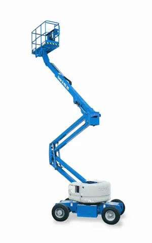
Genie Genie Articulated Boom Lift S-40 HF S-40 HF
Need answers fast?
Explore the manual using AI.

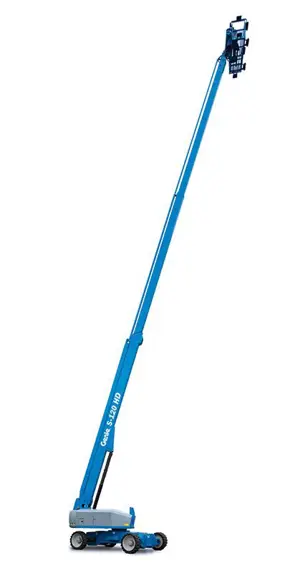
The Genie Articulated Boom Lift S-40 HF is a versatile aerial work platform designed for optimal performance in various industrial applications. Known for its reliability and ease of use, this boom lift provides exceptional reach and maneuverability, making it an essential tool for construction and maintenance tasks.
Turn manuals into instant answers
with your AI-powered assistantTurn manuals into instant answers
with your AI-powered assistant
Manual for Genie Genie Articulated Boom Lift S-40 HF S-40 HF
Complete asset maintenance, one click away
Get instant access to all the maintenance information you need. Empower technicians to perform preventive maintenance with asset packages, ready to use right out of the box.

Documents & Manuals
Find all the essential guides in one place.
 Tensioning Guide
- Belt-diagram
- C-120 pulleys
+ 13 more

Work Order Templates
Pre-built workflows to keep your asset running smoothly.
- Daily Electrical System Inspection
- Replace Roller and Pulley
- Install Engine B-120
+ 29 more

Procedures
Integrate maintenance plans directly into your work orders.
- Motion Industries
- Applied Industrial Technologies
- Electrical Brothers
+ 5 more

Parts
Access the parts list for your equipment in MaintainX.
- Drive Motor
- B2 Rollers
- Tensioning System
+ 40 more
Genie Genie Articulated Boom Lift S-40 HF S-40 HF
Create an account to install this asset package.
Maintenance Plans for Genie Genie Articulated Boom Lift S-40 HF Model S-40 HF
Integrate maintenance plans directly into your work orders in MaintainX.
3 Monthly Recovery System Test
This maintenance procedure applies to the following models: S-100, S-105, S-120, S-125, S-100HD, S-120HD, SX-105 XC, SX-125 XC, SX-135 XC, SX-150, SX-180, Z-80/60, Z-135/70 and ZX-135/70
Perform this procedure with the machine on a firm, level surface with the axles extended
Perform this procedure with all weight, tools, equipment and personnel removed from the platform
If any boom safety limit switches are faulty, the primary boom will only retract and not lower
Turn the key switch to the ground control and pull out the red Emergency Stop button to the on position. Start the engine
Fully raise the secondary boom then extend it approximately 4 ft / 1.2 m (Z-80, Z-135 and ZX-135 models)
Raise the primary boom approximately 15° then extend it approximately 4 ft / 1.2 m (All models)
Turn the key switch to the off position to turn off the engine. Turn the key switch back to ground controls
Remove the key from the main key switch and insert the key into the bypass/recovery key switch

3 Monthly Safety Envelope And Circuit Test
- Test the Safety Envelope and Circuits - Z-80/60
Testing the machine safety envelope is critical to safe machine operation. If the boom is allowed to operate when a safety switch is not functioning correctly, the machine stability is compromised and may tip over
For limit switch and angle sensor information, Refer to appropriate Service and Repair Manual for your machine
Note: Use the following chart to identify the description of each LCD screen control button used in this procedure
Secondary Boom #1 Angle Safety Limit Switch, LSS2AS
1. Turn the key switch to ground control and pull out the red Emergency Stop button to the on position at both ground and platform controls
2. Start the engine from the ground controls
3. Press the (plus)(minus) buttons on the LCD screen to activate status mode
4. Press the enter or previous button on the LCD screen until secondary boom length is displayed
3 Monthly Brake Configuration Check
- Confirm the Proper Brake Configuration
1. Locate the drive hub disconnect cap
2. Check each drive hub disconnect cap to be sure it is in the engaged position
- Test the Drive Brakes
WARNING!
Collision hazard. Be sure that the machine is not in free-wheel or partial free-wheel configuration
Refer to maintenance procedure, Confirm the Proper Brake Configuration
Note: Select a test area that is firm, level and free of obstructions
1. Mark a test line on the ground for reference
2000 Hourly Extendable Axle Wear Pads Check
Warning: Ensure the axles are fully extended before attempting this procedure
Measure each wear pad
Is the wear pad measurement less than 0.437 inch/1.12 mm?
If a wear pad is not less than specification, shim as necessary to obtain minimum clearance and no drag
If any wear pads are replaced, refer to Repair Procedure in the appropriate Service and Repair Manual for your machine, Grease the Extendable Axles
Check for tight spots that may cause binding or scraping of the axle tubes
Sign off on the axle wear pads check
3 Monthly Engine Maintenance
Warning: These procedures do not apply to certain engine models. If RPM or service is required, please contact Genie Product Support
Models with ALC-600 operating system
Start the engine from the ground controls
Press the Home button on the display. Press button 2 under the engine idle icon and select low idle
Press button 1 under the gauges icon. Scroll down to RPM and press Ok
Press button 2 under the engine idle icon and select high idle
Models with ALC-1000 operating system
Start the engine from the ground controls
Press the enter or previous button on the LCD screen until engine rpm is displayed
Parts for Genie Genie Articulated Boom Lift S-40 HF S-40 HF
Access the parts list for your equipment in MaintainX.
O-ring Field Service Kit
49612
Digital Protractor
58377
Digital Level Kit
58351
O-ring Field Service Kit
49612
Digital Protractor
58377
Digital Level Kit
58351
O-ring Field Service Kit
49612
Digital Protractor
58377
Digital Level Kit
58351
Unlock efficiency
with MaintainX CoPilot
MaintainX CoPilot is your expert colleague, on call 24/7, helping your team find the answers they need to keep equipment running.
Reduce Unplanned Downtime
Ensure your team follows consistent procedures to minimize equipment failures and costly delays.
Maximize Asset Availability
Keep your assets running longer and more reliably, with standardized maintenance workflows from OEM manuals.
Lower Maintenance Costs
Turn any technician into an expert to streamline operations, maintain more assets, and reduce overall costs.
Thousands of companies manage their assets with MaintainX

'%3e%3cpath%20fill='url(%23b)'%20d='M66.008%2080.068c-5.084-.786-9.763-3.834-12.442-8.68a16.942%2016.942%200%200%201-1.87-5.18c1.096.19%202.203.476%203.298.87%206.525%202.333%2010.836%207.68%2011.014%2012.99ZM51.47%2061.576c.488-5.524%203.62-10.716%208.847-13.597a17.132%2017.132%200%200%201%2011.335-1.882c-.798%208.145-7.43%2014.848-16.038%2015.599-1.417.119-2.799.07-4.144-.12Zm28.564-11.478a17.513%2017.513%200%200%201%203.727%204.62c4.608%208.335%201.584%2018.813-6.75%2023.409a16.988%2016.988%200%200%201-4.359%201.679%2019.624%2019.624%200%200%201-3.977-12.776c.346-7.561%204.942-13.931%2011.36-16.932Z'/%3e%3cpath%20fill='%23110F0D'%20fill-rule='evenodd'%20d='M142.831%2048.324h4.977V77.03h-4.977V48.324Zm27.278%2013.002c.322%201.048.453%202.263.453%203.62v12.073h-4.787V66.208c0-.75-.047-1.572-.154-2.143-.453-2.382-1.822-3.572-4.215-3.572-2.31%200-3.882%201.274-4.43%203.476-.143.596-.226%201.405-.226%202.25v10.8h-4.787V56.623h4.477v2.989c1.536-2.5%203.906-3.43%206.371-3.43%203.488%200%206.263%201.68%207.298%205.144Zm24.636%207.323c0%203.882-2.358%206.525-5.763%207.727-1.298.453-2.632.643-4.62.643h-10.169V48.324h9.085c1.691%200%203.156.143%204.049.38%203.465.93%205.727%203.68%205.727%207.335%200%202.441-.81%204.156-2.762%205.644%202.905%201.417%204.453%203.727%204.453%206.966Zm-15.634-8.656h4.584c1.024%200%201.917-.143%202.536-.417%201.215-.548%201.905-1.608%201.905-3.167%200-1.548-.643-2.572-1.845-3.132-.691-.31-1.762-.452-2.763-.452h-4.417v7.168Zm10.716%208.465c0-1.536-.893-3.37-3.227-3.893-.428-.095-1.036-.143-1.571-.143h-5.918v8.085h5.501c.56%200%201.429-.048%201.953-.167%201.94-.453%203.262-1.846%203.262-3.882Zm47.747-11.847-8.097%2020.408h-4.429l-8.109-20.408h5.191l5.192%2014.574%205.108-14.574h5.144Zm-20.218%2010.002c0%20.69-.036%201.262-.155%201.94h-15.943c.631%202.87%202.714%204.728%205.882%204.728%202.131%200%203.607-.882%204.703-2.525h4.87c-1.762%204.144-5.204%206.692-9.657%206.692-6.084%200-10.537-4.858-10.537-10.49%200-6.108%204.524-10.776%2010.335-10.776%206.239%200%2010.442%204.954%2010.502%2010.43Zm-4.763-1.405c-.333-2.846-2.643-4.858-5.691-4.858-2.894%200-5.287%201.929-5.621%204.858h11.312Zm-72.667%203.44c0%204.787-3.287%208.371-9.419%208.371H119.363V64.66c-1.917.274-3.87.69-5.811%201.238l4.537%2011.121h-5.418l-3.596-9.585c-5.144%202.084-10.085%205.216-14.217%209.585h-4.786L101.8%2048.312h4.56l5.68%2013.883a44.112%2044.112%200%200%201%207.323-1.774V48.312h9.084c1.703%200%203.156.143%204.061.393%203.453.929%205.727%203.667%205.727%207.323%200%201.917-.738%204.179-2.81%205.691%203.06%201.56%204.501%204.025%204.501%206.93Zm-15.634-8.667a62.664%2062.664%200%200%201%202.06-.036c1.703.012%203.239.131%204.608.37%201.441-.549%202.357-1.727%202.357-3.537%200-1.941-.881-3.144-2.488-3.667-.548-.18-1.358-.286-2.322-.286h-4.215v7.156Zm-16.55%203.905-3.715-9.894-6.394%2016.502c2.833-2.595%206.263-4.858%2010.109-6.608Zm27.254%204.74c0-2.775-3.131-4.347-8.513-4.418-.715%200-1.441.011-2.191.047v8.252h5.918c2.548%200%204.786-1.37%204.786-3.882Z'%20clip-rule='evenodd'/%3e%3c/g%3e%3cdefs%3e%3clinearGradient%20id='b'%20x1='51.47'%20x2='85.916'%20y1='62.946'%20y2='62.946'%20gradientUnits='userSpaceOnUse'%3e%3cstop%20stop-color='%23CD9F28'/%3e%3cstop%20offset='1'%20stop-color='%23ECD80B'/%3e%3c/linearGradient%3e%3cclipPath%20id='a'%3e%3cpath%20fill='%23fff'%20d='M51.47%2045.728h186.104V80.14H51.47z'/%3e%3c/clipPath%3e%3c/defs%3e%3c/svg%3e)


More from Genie


Explore Other Assets


© 2025 MaintainX. All rights reserved.