


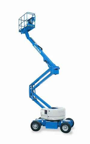
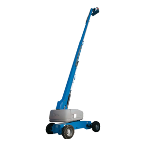
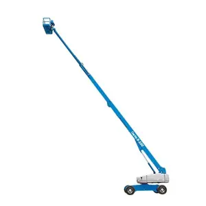
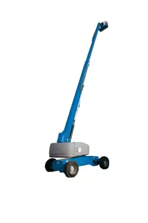
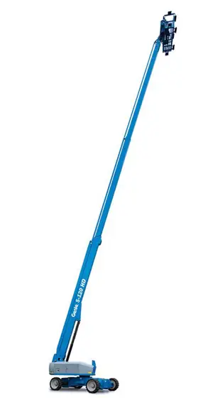
Genie Genie Articulated Boom Lift S-125 S-125
Need answers fast?
Explore the manual using AI.

The Genie Articulated Boom Lift S-125 is a versatile aerial work platform designed for efficient lifting and maneuverability in various industrial applications. Known for its reliability and ease of use, this model ensures safety and productivity on job sites, making it an essential asset for contractors and maintenance teams.
Turn manuals into instant answers
with your AI-powered assistantTurn manuals into instant answers
with your AI-powered assistant
Manual for Genie Genie Articulated Boom Lift S-125 S-125
Complete asset maintenance, one click away
Get instant access to all the maintenance information you need. Empower technicians to perform preventive maintenance with asset packages, ready to use right out of the box.

Documents & Manuals
Find all the essential guides in one place.
 Tensioning Guide
- Belt-diagram
- C-120 pulleys
+ 13 more

Work Order Templates
Pre-built workflows to keep your asset running smoothly.
- Daily Electrical System Inspection
- Replace Roller and Pulley
- Install Engine B-120
+ 29 more

Procedures
Integrate maintenance plans directly into your work orders.
- Motion Industries
- Applied Industrial Technologies
- Electrical Brothers
+ 5 more

Parts
Access the parts list for your equipment in MaintainX.
- Drive Motor
- B2 Rollers
- Tensioning System
+ 40 more
Genie Genie Articulated Boom Lift S-125 S-125
Create an account to install this asset package.
Maintenance Plans for Genie Genie Articulated Boom Lift S-125 Model S-125
Integrate maintenance plans directly into your work orders in MaintainX.
Initial 150 Hours Hydraulic Filter Maintenance
Visual Inspection of the Hydraulic Oil
Inspect the Hydraulic Filters
After performing maintenance, perform scheduled services
Sign off on the hydraulic filter maintenance

2000 Hourly Engine Maintenance
- Perform Engine Maintenance
Required maintenance procedures and additional engine information are available in the manufacturer's manuals. Refer to Specifications, Engine Operator and Maintenance Manuals
Cummins Models:
• Cooling system - flush
• Valve clearance - check/adjust
GM .998L:
• Spark plug wires - replace
• Timing belt - replace
• Bolts, nuts and fasteners - check/tighten
3 Monthly Emergency Power System Test
Turn the key switch to ground control and pull out the red Emergency Stop button to the on position at both the ground and platform controls
At the ground controls, break the security tie and lift the emergency power switch cover (if equipped)
Simultaneously hold the emergency power switch on and operate each boom function through a partial cycle
Close the emergency power switch cover and secure the cover with a security tie (if equipped)
Turn the key switch to platform controls
At the platform controls, break the security tie and lift the emergency power switch cover (if equipped)
Press down on the foot switch and simultaneously hold the emergency power switch on and operate each boom function through a partial cycle
Close the emergency power switch cover and secure the cover with a security tie (if equipped)
Sign off on the emergency power system test
3 Monthly Safety Envelope And Circuits Maintenance
Testing the machine safety envelope is critical to safe machine operation.
Start the engine from the ground controls
Raise the boom to approximately 60°
Extend the boom to more than 80 feet / 24.4 m
Push in the red Emergency Stop button to the off position
Plug in the LSB2RS test jumper between the lower limit switch and the function manifold
Pull out the red Emergency Stop button to the on position and start the engine
Disconnect the 68° proximity switch LSB14A0 and install a wire jumper between pin 3 and pin 4 of the Deutsch connector
Activate the function enable/high RPM button and extend the boom to 101 feet / 30.8 m
1 Yearly Platform Load Sense System Test
Warning: This procedure requires trained personnel with PPE!
Ensure no load sense system faults exist prior to performing this procedure
On a properly functioning machine, the LEDs on both control modules, located next to the ground control box, should be off
All weight, tools, accessories and equipment removed from the platform
Key switch turned to ground control and red Emergency Stop button pulled out to the on position at both ground and platform controls
Engine started from the ground controls
Weight placed on the center of the platform floor (kg)
Amber restricted range of motion LED at the platform controls on and engine running
Additional weight placed on the center of the platform floor (kg)
Parts for Genie Genie Articulated Boom Lift S-125 S-125
Access the parts list for your equipment in MaintainX.
O-ring Field Service Kit
49612
Digital Protractor
58377
Digital Level Kit
58351
O-ring Field Service Kit
49612
Digital Protractor
58377
Digital Level Kit
58351
O-ring Field Service Kit
49612
Digital Protractor
58377
Digital Level Kit
58351
Unlock efficiency
with MaintainX CoPilot
MaintainX CoPilot is your expert colleague, on call 24/7, helping your team find the answers they need to keep equipment running.
Reduce Unplanned Downtime
Ensure your team follows consistent procedures to minimize equipment failures and costly delays.
Maximize Asset Availability
Keep your assets running longer and more reliably, with standardized maintenance workflows from OEM manuals.
Lower Maintenance Costs
Turn any technician into an expert to streamline operations, maintain more assets, and reduce overall costs.
Thousands of companies manage their assets with MaintainX

'%3e%3cpath%20fill='url(%23b)'%20d='M66.008%2080.068c-5.084-.786-9.763-3.834-12.442-8.68a16.942%2016.942%200%200%201-1.87-5.18c1.096.19%202.203.476%203.298.87%206.525%202.333%2010.836%207.68%2011.014%2012.99ZM51.47%2061.576c.488-5.524%203.62-10.716%208.847-13.597a17.132%2017.132%200%200%201%2011.335-1.882c-.798%208.145-7.43%2014.848-16.038%2015.599-1.417.119-2.799.07-4.144-.12Zm28.564-11.478a17.513%2017.513%200%200%201%203.727%204.62c4.608%208.335%201.584%2018.813-6.75%2023.409a16.988%2016.988%200%200%201-4.359%201.679%2019.624%2019.624%200%200%201-3.977-12.776c.346-7.561%204.942-13.931%2011.36-16.932Z'/%3e%3cpath%20fill='%23110F0D'%20fill-rule='evenodd'%20d='M142.831%2048.324h4.977V77.03h-4.977V48.324Zm27.278%2013.002c.322%201.048.453%202.263.453%203.62v12.073h-4.787V66.208c0-.75-.047-1.572-.154-2.143-.453-2.382-1.822-3.572-4.215-3.572-2.31%200-3.882%201.274-4.43%203.476-.143.596-.226%201.405-.226%202.25v10.8h-4.787V56.623h4.477v2.989c1.536-2.5%203.906-3.43%206.371-3.43%203.488%200%206.263%201.68%207.298%205.144Zm24.636%207.323c0%203.882-2.358%206.525-5.763%207.727-1.298.453-2.632.643-4.62.643h-10.169V48.324h9.085c1.691%200%203.156.143%204.049.38%203.465.93%205.727%203.68%205.727%207.335%200%202.441-.81%204.156-2.762%205.644%202.905%201.417%204.453%203.727%204.453%206.966Zm-15.634-8.656h4.584c1.024%200%201.917-.143%202.536-.417%201.215-.548%201.905-1.608%201.905-3.167%200-1.548-.643-2.572-1.845-3.132-.691-.31-1.762-.452-2.763-.452h-4.417v7.168Zm10.716%208.465c0-1.536-.893-3.37-3.227-3.893-.428-.095-1.036-.143-1.571-.143h-5.918v8.085h5.501c.56%200%201.429-.048%201.953-.167%201.94-.453%203.262-1.846%203.262-3.882Zm47.747-11.847-8.097%2020.408h-4.429l-8.109-20.408h5.191l5.192%2014.574%205.108-14.574h5.144Zm-20.218%2010.002c0%20.69-.036%201.262-.155%201.94h-15.943c.631%202.87%202.714%204.728%205.882%204.728%202.131%200%203.607-.882%204.703-2.525h4.87c-1.762%204.144-5.204%206.692-9.657%206.692-6.084%200-10.537-4.858-10.537-10.49%200-6.108%204.524-10.776%2010.335-10.776%206.239%200%2010.442%204.954%2010.502%2010.43Zm-4.763-1.405c-.333-2.846-2.643-4.858-5.691-4.858-2.894%200-5.287%201.929-5.621%204.858h11.312Zm-72.667%203.44c0%204.787-3.287%208.371-9.419%208.371H119.363V64.66c-1.917.274-3.87.69-5.811%201.238l4.537%2011.121h-5.418l-3.596-9.585c-5.144%202.084-10.085%205.216-14.217%209.585h-4.786L101.8%2048.312h4.56l5.68%2013.883a44.112%2044.112%200%200%201%207.323-1.774V48.312h9.084c1.703%200%203.156.143%204.061.393%203.453.929%205.727%203.667%205.727%207.323%200%201.917-.738%204.179-2.81%205.691%203.06%201.56%204.501%204.025%204.501%206.93Zm-15.634-8.667a62.664%2062.664%200%200%201%202.06-.036c1.703.012%203.239.131%204.608.37%201.441-.549%202.357-1.727%202.357-3.537%200-1.941-.881-3.144-2.488-3.667-.548-.18-1.358-.286-2.322-.286h-4.215v7.156Zm-16.55%203.905-3.715-9.894-6.394%2016.502c2.833-2.595%206.263-4.858%2010.109-6.608Zm27.254%204.74c0-2.775-3.131-4.347-8.513-4.418-.715%200-1.441.011-2.191.047v8.252h5.918c2.548%200%204.786-1.37%204.786-3.882Z'%20clip-rule='evenodd'/%3e%3c/g%3e%3cdefs%3e%3clinearGradient%20id='b'%20x1='51.47'%20x2='85.916'%20y1='62.946'%20y2='62.946'%20gradientUnits='userSpaceOnUse'%3e%3cstop%20stop-color='%23CD9F28'/%3e%3cstop%20offset='1'%20stop-color='%23ECD80B'/%3e%3c/linearGradient%3e%3cclipPath%20id='a'%3e%3cpath%20fill='%23fff'%20d='M51.47%2045.728h186.104V80.14H51.47z'/%3e%3c/clipPath%3e%3c/defs%3e%3c/svg%3e)


More from Genie


Explore Other Assets


© 2025 MaintainX. All rights reserved.