


Genie Articulated Boom Lift Z-34/22 DC
Need answers fast?
Explore the manual using AI.
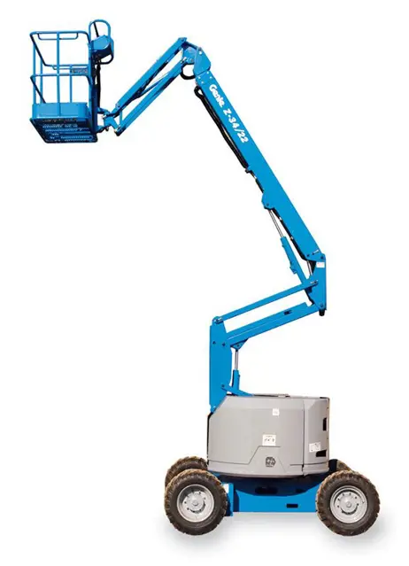
The Genie Articulated Boom Lift Z-34/22 DC is a versatile and reliable aerial work platform designed for efficient operation in various environments. Known for its compact design and exceptional reach, this boom lift is ideal for construction, maintenance, and industrial applications, ensuring safety and productivity on the job site.
Turn manuals into instant answers
with your AI-powered assistantTurn manuals into instant answers
with your AI-powered assistant
Manual for Genie Articulated Boom Lift Z-34/22 DC
Complete asset maintenance, one click away
Get instant access to all the maintenance information you need. Empower technicians to perform preventive maintenance with asset packages, ready to use right out of the box.

Documents & Manuals
Find all the essential guides in one place.
 Tensioning Guide
- Belt-diagram
- C-120 pulleys
+ 13 more

Work Order Templates
Pre-built workflows to keep your asset running smoothly.
- Daily Electrical System Inspection
- Replace Roller and Pulley
- Install Engine B-120
+ 29 more

Procedures
Integrate maintenance plans directly into your work orders.
- Motion Industries
- Applied Industrial Technologies
- Electrical Brothers
+ 5 more

Parts
Access the parts list for your equipment in MaintainX.
- Drive Motor
- B2 Rollers
- Tensioning System
+ 40 more
Genie Articulated Boom Lift Z-34/22 DC
Create an account to install this asset package.
Maintenance Plans for Genie Articulated Boom Lift Model Z-34/22 DC
Integrate maintenance plans directly into your work orders in MaintainX.
Engine RPM Inspection
Warning: Two people are required to perform this procedure.
Perform this procedure with the engine at normal operating temperature.
Connect an rpm gauge to the engine, and then start the engine from the ground controls. Enter the rpm reading.
Is the low idle rpm 2000?
If the low idle rpm is not correct, proceed to step 6.
Did you adjust the low idle rpm by loosening the lock nut and turning the low idle adjustment screw?
Recheck the rpm after adjustment. Enter the new rpm reading.
Move the engine idle control switch to high idle (rabbit symbol) from the ground controls. Is the high idle rpm 3000?
If the high idle rpm is not correct, proceed to step 10.

Platform Self-Leveling Testing
Warning: This procedure requires trained personnel!
Key switch turned to ground control and red Emergency Stop button in the on position
Boom lowered to the stowed position
Platform adjusted to a level position
Primary boom raised and lowered through a full cycle
Enter the platform level in degrees
Sign off on the platform self-leveling test
Drive Brakes Testing
Warning: Collision hazard. Be sure that the machine is not in free-wheel or partial free-wheel configuration. Refer to maintenance procedure, Confirm the Proper Brake Configuration.
Note: Select a test area that is firm, level and free of obstructions.
Mark a test line on the ground for reference.
Lower the boom to the stowed position.
Turn the key switch to platform controls.
Choose a point on the machine (i.e., contact patch of a tire) as a visual reference for use when crossing the test line.
Bring the machine to top drive speed before reaching the test line. Release the drive joystick when your reference point on the machine crosses the test line.
Measure the distance between the test line and your machine reference point.
Note: The brakes must be able to hold the machine on any slope it is able to climb.
Engine Idle Select Operation Testing
Pull out the red Emergency Stop button to the on position at both the ground and platform controls.
Start the engine from the ground controls. Then move the engine idle control switch to high idle (rabbit symbol) and hold in the on position.
Release the engine idle control switch.
Turn the key switch to platform controls.
Move the engine idle control switch to high idle (rabbit symbol).
Move the engine idle control switch to low idle (turtle symbol).
Move the engine idle select switch to foot switch activated high idle (rabbit and foot switch symbol).
Press down the foot switch.
Sign off on the Engine Idle Select Operation Testing
Glow Plugs Check
Connect the leads from an ohmmeter between the far left glow plug and ground.
Enter the resistance reading. The resistance should be approximately 1Ω.
If the ohm reading is different than 1Ω, remove the wire and connector plate from the three individual glow plugs. Then, one glow plug at a time, measure the resistance between the glow plug and ground.
Enter the resistance reading for each individual glow plug. The resistance should be approximately 1.8Ω for each individual glow plug.
Turn the key switch to ground control and pull out the red Emergency Stop button to the on position.
Connect the red positive (+) lead from a volt meter to one of the glow plugs. Connect the black negative (-) lead to ground.
Hold the glow plug switch in the on position.
Enter the volt meter reading. The volt meter should read 12V DC or more.
Repeat steps 4 and 5 for the other glow plug.
Parts for Genie Articulated Boom Lift Z-34/22 DC
Access the parts list for your equipment in MaintainX.
Resistor
27287
O-ring Field Service Kit
49612
Operator's Manual
139420
Operator and Maintenance Manual
52958
Resistor
27287
O-ring Field Service Kit
49612
Operator's Manual
139420
Operator and Maintenance Manual
52958
Resistor
27287
O-ring Field Service Kit
49612
Operator's Manual
139420
Operator and Maintenance Manual
52958
Unlock efficiency
with MaintainX CoPilot
MaintainX CoPilot is your expert colleague, on call 24/7, helping your team find the answers they need to keep equipment running.
Reduce Unplanned Downtime
Ensure your team follows consistent procedures to minimize equipment failures and costly delays.
Maximize Asset Availability
Keep your assets running longer and more reliably, with standardized maintenance workflows from OEM manuals.
Lower Maintenance Costs
Turn any technician into an expert to streamline operations, maintain more assets, and reduce overall costs.
Thousands of companies manage their assets with MaintainX

'%3e%3cpath%20fill='url(%23b)'%20d='M66.008%2080.068c-5.084-.786-9.763-3.834-12.442-8.68a16.942%2016.942%200%200%201-1.87-5.18c1.096.19%202.203.476%203.298.87%206.525%202.333%2010.836%207.68%2011.014%2012.99ZM51.47%2061.576c.488-5.524%203.62-10.716%208.847-13.597a17.132%2017.132%200%200%201%2011.335-1.882c-.798%208.145-7.43%2014.848-16.038%2015.599-1.417.119-2.799.07-4.144-.12Zm28.564-11.478a17.513%2017.513%200%200%201%203.727%204.62c4.608%208.335%201.584%2018.813-6.75%2023.409a16.988%2016.988%200%200%201-4.359%201.679%2019.624%2019.624%200%200%201-3.977-12.776c.346-7.561%204.942-13.931%2011.36-16.932Z'/%3e%3cpath%20fill='%23110F0D'%20fill-rule='evenodd'%20d='M142.831%2048.324h4.977V77.03h-4.977V48.324Zm27.278%2013.002c.322%201.048.453%202.263.453%203.62v12.073h-4.787V66.208c0-.75-.047-1.572-.154-2.143-.453-2.382-1.822-3.572-4.215-3.572-2.31%200-3.882%201.274-4.43%203.476-.143.596-.226%201.405-.226%202.25v10.8h-4.787V56.623h4.477v2.989c1.536-2.5%203.906-3.43%206.371-3.43%203.488%200%206.263%201.68%207.298%205.144Zm24.636%207.323c0%203.882-2.358%206.525-5.763%207.727-1.298.453-2.632.643-4.62.643h-10.169V48.324h9.085c1.691%200%203.156.143%204.049.38%203.465.93%205.727%203.68%205.727%207.335%200%202.441-.81%204.156-2.762%205.644%202.905%201.417%204.453%203.727%204.453%206.966Zm-15.634-8.656h4.584c1.024%200%201.917-.143%202.536-.417%201.215-.548%201.905-1.608%201.905-3.167%200-1.548-.643-2.572-1.845-3.132-.691-.31-1.762-.452-2.763-.452h-4.417v7.168Zm10.716%208.465c0-1.536-.893-3.37-3.227-3.893-.428-.095-1.036-.143-1.571-.143h-5.918v8.085h5.501c.56%200%201.429-.048%201.953-.167%201.94-.453%203.262-1.846%203.262-3.882Zm47.747-11.847-8.097%2020.408h-4.429l-8.109-20.408h5.191l5.192%2014.574%205.108-14.574h5.144Zm-20.218%2010.002c0%20.69-.036%201.262-.155%201.94h-15.943c.631%202.87%202.714%204.728%205.882%204.728%202.131%200%203.607-.882%204.703-2.525h4.87c-1.762%204.144-5.204%206.692-9.657%206.692-6.084%200-10.537-4.858-10.537-10.49%200-6.108%204.524-10.776%2010.335-10.776%206.239%200%2010.442%204.954%2010.502%2010.43Zm-4.763-1.405c-.333-2.846-2.643-4.858-5.691-4.858-2.894%200-5.287%201.929-5.621%204.858h11.312Zm-72.667%203.44c0%204.787-3.287%208.371-9.419%208.371H119.363V64.66c-1.917.274-3.87.69-5.811%201.238l4.537%2011.121h-5.418l-3.596-9.585c-5.144%202.084-10.085%205.216-14.217%209.585h-4.786L101.8%2048.312h4.56l5.68%2013.883a44.112%2044.112%200%200%201%207.323-1.774V48.312h9.084c1.703%200%203.156.143%204.061.393%203.453.929%205.727%203.667%205.727%207.323%200%201.917-.738%204.179-2.81%205.691%203.06%201.56%204.501%204.025%204.501%206.93Zm-15.634-8.667a62.664%2062.664%200%200%201%202.06-.036c1.703.012%203.239.131%204.608.37%201.441-.549%202.357-1.727%202.357-3.537%200-1.941-.881-3.144-2.488-3.667-.548-.18-1.358-.286-2.322-.286h-4.215v7.156Zm-16.55%203.905-3.715-9.894-6.394%2016.502c2.833-2.595%206.263-4.858%2010.109-6.608Zm27.254%204.74c0-2.775-3.131-4.347-8.513-4.418-.715%200-1.441.011-2.191.047v8.252h5.918c2.548%200%204.786-1.37%204.786-3.882Z'%20clip-rule='evenodd'/%3e%3c/g%3e%3cdefs%3e%3clinearGradient%20id='b'%20x1='51.47'%20x2='85.916'%20y1='62.946'%20y2='62.946'%20gradientUnits='userSpaceOnUse'%3e%3cstop%20stop-color='%23CD9F28'/%3e%3cstop%20offset='1'%20stop-color='%23ECD80B'/%3e%3c/linearGradient%3e%3cclipPath%20id='a'%3e%3cpath%20fill='%23fff'%20d='M51.47%2045.728h186.104V80.14H51.47z'/%3e%3c/clipPath%3e%3c/defs%3e%3c/svg%3e)


More from Genie


Explore Other Assets


© 2026 MaintainX. All rights reserved.