


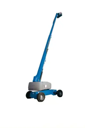
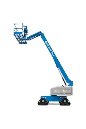
Genie Articulated Boom Lift Z-30/20N RJ
Need answers fast?
Explore the manual using AI.
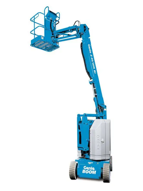
The Genie Articulated Boom Lift Z-30/20N RJ is a versatile aerial work platform designed for efficient operation in tight spaces. This reliable equipment from Genie offers exceptional reach and maneuverability, making it ideal for construction, maintenance, and industrial applications.
Turn manuals into instant answers
with your AI-powered assistantTurn manuals into instant answers
with your AI-powered assistant
Manual for Genie Articulated Boom Lift Z-30/20N RJ
Complete asset maintenance, one click away
Get instant access to all the maintenance information you need. Empower technicians to perform preventive maintenance with asset packages, ready to use right out of the box.

Documents & Manuals
Find all the essential guides in one place.
 Tensioning Guide
- Belt-diagram
- C-120 pulleys
+ 13 more

Work Order Templates
Pre-built workflows to keep your asset running smoothly.
- Daily Electrical System Inspection
- Replace Roller and Pulley
- Install Engine B-120
+ 29 more

Procedures
Integrate maintenance plans directly into your work orders.
- Motion Industries
- Applied Industrial Technologies
- Electrical Brothers
+ 5 more

Parts
Access the parts list for your equipment in MaintainX.
- Drive Motor
- B2 Rollers
- Tensioning System
+ 40 more
Genie Articulated Boom Lift Z-30/20N RJ
Create an account to install this asset package.
Maintenance Plans for Genie Articulated Boom Lift Model Z-30/20N RJ
Integrate maintenance plans directly into your work orders in MaintainX.
Drive Brakes Testing
Warning: Collision hazard. Be sure that the machine is not in free-wheel or partial free-wheel configuration.
Test area is firm, level and free of obstructions
Upload a photo of the marked test line on the ground
Boom is in the stowed position
Key switch is turned to platform controls
Machine reached top drive speed before reaching the test line
Distance between the test line and your machine reference point
Brakes able to hold the machine on any slope it is able to climb
Sign off on the brake test

Free-wheel Configuration Check
Warning: Collision hazard. Select a work site that is firm and level.
Notice: Component damage hazard. If the machine must be towed, do not exceed 2 mph / 3.2 km/h.
Steer wheels chocked to prevent the machine from rolling
Lifting jack of ample capacity (15,000 lbs / 7000 kg) centered under the drive chassis between the non-steer wheels
Wheels lifted off the ground and blocks placed under the drive chassis for support
Drive hubs disengaged by turning over the drive hub disconnect caps on each non-steer wheel hub
Each non-steer wheel manually rotated
Each non-steer wheel rotates with minimum effort
Drive hubs engaged by turning over the drive hub disconnect caps
Electrical Wiring Inspection
Warning: Electrocution/burn hazard. Contact with hot or live circuits could result in death or serious injury. Remove all rings, watches and other jewelry.
Remove the drive chassis cover from the non-steer end of the machine.
Inspect the following areas for burnt, chafed, corroded and loose wires: Electrical power panel, Electrical relay panel, Ground control panel, Function manifold wiring
Turn the key switch to ground controls and pull out the red Emergency Stop button to the on position at both the ground and platform controls.
Raise the secondary boom until the mid-pivot is approximately 10 feet / 3 m off the ground.
Inspect the turntable center area for burnt, chafed and pinched cables.
Lower the boom to the stowed position and turn the machine off.
Inspect the following areas for burnt, chafed, corroded, pinched and loose wires: Cable track on the primary boom, Primary boom to platform cable harness, Inside of the platform control box
Inspect for a liberal coating of dielectric grease at the following location: All wire harness connectors to the platform control box, All wire harness connectors located under the ground control side turntable cover, Harness connector to the drive motor controller located in the non-steer end of the drive chassis.
Ground Control Override Testing
Warning: This procedure should be performed every 250 hours or quarterly, whichever comes first.
Push in the red Emergency Stop button at the platform controls to the off position.
Turn the key switch to ground controls and pull out the red Emergency Stop button to the on position.
Operate each boom function through a partial cycle at the ground controls.
Did all boom functions operate?
Sign off on the ground control override testing
Batteries Check
Warning: This procedure requires protective clothing and eye wear.
Disconnect each battery pack from the machine.
Release the battery pack latches and rotate each battery pack out and away from the chassis.
Remove the cover from each battery box.
Battery cable connections are free of corrosion.
Battery retainers and cable connections are tight.
Fully charge the batteries.
Allow the batteries to rest 24 hours before continuing this procedure to allow the battery cells to equalize.
Remove the battery vent caps and check the specific gravity of each battery cell with a hydrometer.
Parts for Genie Articulated Boom Lift Z-30/20N RJ
Access the parts list for your equipment in MaintainX.
Z-30/20N Service Manual
139378
Lift Cylinder Safety Chock
36555
Z-30/20N Service Manual
35532
Motor Controller Programmer
56303
O-ring Field Service Kit
49612
Z-30/20N Service Manual
139378
Lift Cylinder Safety Chock
36555
Z-30/20N Service Manual
35532
Motor Controller Programmer
56303
O-ring Field Service Kit
49612
Z-30/20N Service Manual
139378
Lift Cylinder Safety Chock
36555
Z-30/20N Service Manual
35532
Motor Controller Programmer
56303
O-ring Field Service Kit
49612
Unlock efficiency
with MaintainX CoPilot
MaintainX CoPilot is your expert colleague, on call 24/7, helping your team find the answers they need to keep equipment running.
Reduce Unplanned Downtime
Ensure your team follows consistent procedures to minimize equipment failures and costly delays.
Maximize Asset Availability
Keep your assets running longer and more reliably, with standardized maintenance workflows from OEM manuals.
Lower Maintenance Costs
Turn any technician into an expert to streamline operations, maintain more assets, and reduce overall costs.
Thousands of companies manage their assets with MaintainX

'%3e%3cpath%20fill='url(%23b)'%20d='M66.008%2080.068c-5.084-.786-9.763-3.834-12.442-8.68a16.942%2016.942%200%200%201-1.87-5.18c1.096.19%202.203.476%203.298.87%206.525%202.333%2010.836%207.68%2011.014%2012.99ZM51.47%2061.576c.488-5.524%203.62-10.716%208.847-13.597a17.132%2017.132%200%200%201%2011.335-1.882c-.798%208.145-7.43%2014.848-16.038%2015.599-1.417.119-2.799.07-4.144-.12Zm28.564-11.478a17.513%2017.513%200%200%201%203.727%204.62c4.608%208.335%201.584%2018.813-6.75%2023.409a16.988%2016.988%200%200%201-4.359%201.679%2019.624%2019.624%200%200%201-3.977-12.776c.346-7.561%204.942-13.931%2011.36-16.932Z'/%3e%3cpath%20fill='%23110F0D'%20fill-rule='evenodd'%20d='M142.831%2048.324h4.977V77.03h-4.977V48.324Zm27.278%2013.002c.322%201.048.453%202.263.453%203.62v12.073h-4.787V66.208c0-.75-.047-1.572-.154-2.143-.453-2.382-1.822-3.572-4.215-3.572-2.31%200-3.882%201.274-4.43%203.476-.143.596-.226%201.405-.226%202.25v10.8h-4.787V56.623h4.477v2.989c1.536-2.5%203.906-3.43%206.371-3.43%203.488%200%206.263%201.68%207.298%205.144Zm24.636%207.323c0%203.882-2.358%206.525-5.763%207.727-1.298.453-2.632.643-4.62.643h-10.169V48.324h9.085c1.691%200%203.156.143%204.049.38%203.465.93%205.727%203.68%205.727%207.335%200%202.441-.81%204.156-2.762%205.644%202.905%201.417%204.453%203.727%204.453%206.966Zm-15.634-8.656h4.584c1.024%200%201.917-.143%202.536-.417%201.215-.548%201.905-1.608%201.905-3.167%200-1.548-.643-2.572-1.845-3.132-.691-.31-1.762-.452-2.763-.452h-4.417v7.168Zm10.716%208.465c0-1.536-.893-3.37-3.227-3.893-.428-.095-1.036-.143-1.571-.143h-5.918v8.085h5.501c.56%200%201.429-.048%201.953-.167%201.94-.453%203.262-1.846%203.262-3.882Zm47.747-11.847-8.097%2020.408h-4.429l-8.109-20.408h5.191l5.192%2014.574%205.108-14.574h5.144Zm-20.218%2010.002c0%20.69-.036%201.262-.155%201.94h-15.943c.631%202.87%202.714%204.728%205.882%204.728%202.131%200%203.607-.882%204.703-2.525h4.87c-1.762%204.144-5.204%206.692-9.657%206.692-6.084%200-10.537-4.858-10.537-10.49%200-6.108%204.524-10.776%2010.335-10.776%206.239%200%2010.442%204.954%2010.502%2010.43Zm-4.763-1.405c-.333-2.846-2.643-4.858-5.691-4.858-2.894%200-5.287%201.929-5.621%204.858h11.312Zm-72.667%203.44c0%204.787-3.287%208.371-9.419%208.371H119.363V64.66c-1.917.274-3.87.69-5.811%201.238l4.537%2011.121h-5.418l-3.596-9.585c-5.144%202.084-10.085%205.216-14.217%209.585h-4.786L101.8%2048.312h4.56l5.68%2013.883a44.112%2044.112%200%200%201%207.323-1.774V48.312h9.084c1.703%200%203.156.143%204.061.393%203.453.929%205.727%203.667%205.727%207.323%200%201.917-.738%204.179-2.81%205.691%203.06%201.56%204.501%204.025%204.501%206.93Zm-15.634-8.667a62.664%2062.664%200%200%201%202.06-.036c1.703.012%203.239.131%204.608.37%201.441-.549%202.357-1.727%202.357-3.537%200-1.941-.881-3.144-2.488-3.667-.548-.18-1.358-.286-2.322-.286h-4.215v7.156Zm-16.55%203.905-3.715-9.894-6.394%2016.502c2.833-2.595%206.263-4.858%2010.109-6.608Zm27.254%204.74c0-2.775-3.131-4.347-8.513-4.418-.715%200-1.441.011-2.191.047v8.252h5.918c2.548%200%204.786-1.37%204.786-3.882Z'%20clip-rule='evenodd'/%3e%3c/g%3e%3cdefs%3e%3clinearGradient%20id='b'%20x1='51.47'%20x2='85.916'%20y1='62.946'%20y2='62.946'%20gradientUnits='userSpaceOnUse'%3e%3cstop%20stop-color='%23CD9F28'/%3e%3cstop%20offset='1'%20stop-color='%23ECD80B'/%3e%3c/linearGradient%3e%3cclipPath%20id='a'%3e%3cpath%20fill='%23fff'%20d='M51.47%2045.728h186.104V80.14H51.47z'/%3e%3c/clipPath%3e%3c/defs%3e%3c/svg%3e)


More from Genie


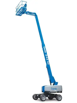

Explore Other Assets


© 2026 MaintainX. All rights reserved.