


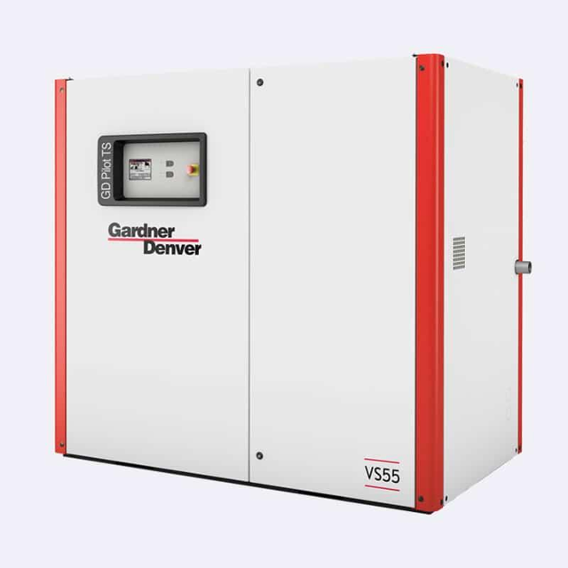
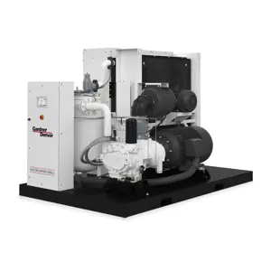
Gardner Denver Screw Air Compressor VS55
Need answers fast?
Explore the manual using AI.
Turn manuals into instant answers
with your AI-powered assistantTurn manuals into instant answers
with your AI-powered assistant
Manual for Gardner Denver Screw Air Compressor VS55
Complete asset maintenance, one click away
Get instant access to all the maintenance information you need. Empower technicians to perform preventive maintenance with asset packages, ready to use right out of the box.

Documents & Manuals
Find all the essential guides in one place.
 Tensioning Guide
- Belt-diagram
- C-120 pulleys
+ 13 more

Work Order Templates
Pre-built workflows to keep your asset running smoothly.
- Daily Electrical System Inspection
- Replace Roller and Pulley
- Install Engine B-120
+ 29 more

Procedures
Integrate maintenance plans directly into your work orders.
- Motion Industries
- Applied Industrial Technologies
- Electrical Brothers
+ 5 more

Parts
Access the parts list for your equipment in MaintainX.
- Drive Motor
- B2 Rollers
- Tensioning System
+ 40 more
Gardner Denver Screw Air Compressor VS55
Create an account to install this asset package.
Maintenance Plans for Gardner Denver Screw Air Compressor Model VS55
Integrate maintenance plans directly into your work orders in MaintainX.
Compressor Filter Cleaning
Cleaning:
Clean the filter mat by brushing or washing.
Important
Never install the filter mat in a wet or moist state!
c) Inlet filter to control cabinet (only VS 55-VS 75)
• Open the louvred grilles of the inlet filter (Fig. 27).
• Remove the filter pad.
• Insert the new filter pad into the louvred grille.
Ensure that the smooth side (-A- Fig. 27) of the filter pad faces the air inlet side.

3000 Hourly / 1 Yearly Safety Valve Testing
Testing the safety valve
The valve should be tested on a separate compressed air line in accordance with local legislation.
Operate the safety valve (- 1 - Fig. 24), depending on the type of valve:
• Slightly turn the valve cap (-2- Fig. 24) (1-2 turns), and then re-close it.
• Actuation of the bleeding lever/pulling ring
Warning
Never operate a screw compressor system with a defective safety valve or without safety valve!;
Oil Level Check
Warning: Only check the oil level when the screw compressor unit is out of operation and depressurized! The pressure reservoir can be under pressure and the oil hot. Warning: Danger of scalding!
Important: Do not spill oil! Check for leakage!
Important: Do not mix oils of different specifications.
Machines which are delivered without oil must first be filled to the max. mark in the pressure reservoir sight glass (see also chapters 8.4 and 8.15)
Stop the compressor, with the stop button.
Wait at least 5 minutes for the oil to settle and for the air to disperse
The oil level is checked with the help of the transparent plastic tube at the pressure reservoir (- 2 - Fig. 14) after every stop and at regular intervals. If required, top up oil
The oil level must be between the maximum level (- 3 - Fig. 14) and minimum level (- 4 - Fig. 14) marked on the oil reservoir.
Also see chapter 8 “Service and maintenance”;
Connecting Terminals Check
Danger: Danger of electric shock! Work on the control cabinet may only be carried out by electrotechnical specialist personnel.
When carrying out adjustment work on the control power transformer, the unit must be electrically isolated and locked off.
Only VS 55-VS 75: Danger of electric shock from loaded condensers! Please always first disconnect the system from the power supply and wait another 10 minutes before touching the electrical components.
Important: A wrong setting of the control-power transformer jeopardizes the trouble-free operation of compressor units and can result in malfunction or damage.
The verification of the control-power transformer setting is a must during commissioning and periodic inspection/ maintenance, as the voltage supply conditions may vary.
The connecting terminals in the switch cabinet have to be checked and, if required, re-tightened during first commissioning and later on in line with the maintenance schedule.
Switch the unit on as described in Chapter 7.4.
Check the control transformer output voltages while operating under load.
Switch the unit off as described in Chapter 7.6.
3000 Hourly / 1 Yearly Compressor Filter Replacement
Perform filter mat change as follows:
a) Filter mat, cooling-air inlet
• Remove fixing screws (- 2 - Fig. 27).
• Remove filter mat (- 1 - Fig. 27) and clean, exchange if damaged.
• Re-insert filter mat in sound insulating panel (- 3 - Fig. 27).
• Secure filter mat by means of fixing screws.
b) Filter mat of optional dryer
• Remove fixing screws (-5- Fig. 27) and remove cover plate (-4- Fig. 27).
• Loosen locknuts and remove filter mat of optional dryer (-6- Fig. 27) and clean or, in the case of damage, replace.
Unlock efficiency
with MaintainX CoPilot
MaintainX CoPilot is your expert colleague, on call 24/7, helping your team find the answers they need to keep equipment running.
Reduce Unplanned Downtime
Ensure your team follows consistent procedures to minimize equipment failures and costly delays.
Maximize Asset Availability
Keep your assets running longer and more reliably, with standardized maintenance workflows from OEM manuals.
Lower Maintenance Costs
Turn any technician into an expert to streamline operations, maintain more assets, and reduce overall costs.
Thousands of companies manage their assets with MaintainX

'%3e%3cpath%20fill='url(%23b)'%20d='M66.008%2080.068c-5.084-.786-9.763-3.834-12.442-8.68a16.942%2016.942%200%200%201-1.87-5.18c1.096.19%202.203.476%203.298.87%206.525%202.333%2010.836%207.68%2011.014%2012.99ZM51.47%2061.576c.488-5.524%203.62-10.716%208.847-13.597a17.132%2017.132%200%200%201%2011.335-1.882c-.798%208.145-7.43%2014.848-16.038%2015.599-1.417.119-2.799.07-4.144-.12Zm28.564-11.478a17.513%2017.513%200%200%201%203.727%204.62c4.608%208.335%201.584%2018.813-6.75%2023.409a16.988%2016.988%200%200%201-4.359%201.679%2019.624%2019.624%200%200%201-3.977-12.776c.346-7.561%204.942-13.931%2011.36-16.932Z'/%3e%3cpath%20fill='%23110F0D'%20fill-rule='evenodd'%20d='M142.831%2048.324h4.977V77.03h-4.977V48.324Zm27.278%2013.002c.322%201.048.453%202.263.453%203.62v12.073h-4.787V66.208c0-.75-.047-1.572-.154-2.143-.453-2.382-1.822-3.572-4.215-3.572-2.31%200-3.882%201.274-4.43%203.476-.143.596-.226%201.405-.226%202.25v10.8h-4.787V56.623h4.477v2.989c1.536-2.5%203.906-3.43%206.371-3.43%203.488%200%206.263%201.68%207.298%205.144Zm24.636%207.323c0%203.882-2.358%206.525-5.763%207.727-1.298.453-2.632.643-4.62.643h-10.169V48.324h9.085c1.691%200%203.156.143%204.049.38%203.465.93%205.727%203.68%205.727%207.335%200%202.441-.81%204.156-2.762%205.644%202.905%201.417%204.453%203.727%204.453%206.966Zm-15.634-8.656h4.584c1.024%200%201.917-.143%202.536-.417%201.215-.548%201.905-1.608%201.905-3.167%200-1.548-.643-2.572-1.845-3.132-.691-.31-1.762-.452-2.763-.452h-4.417v7.168Zm10.716%208.465c0-1.536-.893-3.37-3.227-3.893-.428-.095-1.036-.143-1.571-.143h-5.918v8.085h5.501c.56%200%201.429-.048%201.953-.167%201.94-.453%203.262-1.846%203.262-3.882Zm47.747-11.847-8.097%2020.408h-4.429l-8.109-20.408h5.191l5.192%2014.574%205.108-14.574h5.144Zm-20.218%2010.002c0%20.69-.036%201.262-.155%201.94h-15.943c.631%202.87%202.714%204.728%205.882%204.728%202.131%200%203.607-.882%204.703-2.525h4.87c-1.762%204.144-5.204%206.692-9.657%206.692-6.084%200-10.537-4.858-10.537-10.49%200-6.108%204.524-10.776%2010.335-10.776%206.239%200%2010.442%204.954%2010.502%2010.43Zm-4.763-1.405c-.333-2.846-2.643-4.858-5.691-4.858-2.894%200-5.287%201.929-5.621%204.858h11.312Zm-72.667%203.44c0%204.787-3.287%208.371-9.419%208.371H119.363V64.66c-1.917.274-3.87.69-5.811%201.238l4.537%2011.121h-5.418l-3.596-9.585c-5.144%202.084-10.085%205.216-14.217%209.585h-4.786L101.8%2048.312h4.56l5.68%2013.883a44.112%2044.112%200%200%201%207.323-1.774V48.312h9.084c1.703%200%203.156.143%204.061.393%203.453.929%205.727%203.667%205.727%207.323%200%201.917-.738%204.179-2.81%205.691%203.06%201.56%204.501%204.025%204.501%206.93Zm-15.634-8.667a62.664%2062.664%200%200%201%202.06-.036c1.703.012%203.239.131%204.608.37%201.441-.549%202.357-1.727%202.357-3.537%200-1.941-.881-3.144-2.488-3.667-.548-.18-1.358-.286-2.322-.286h-4.215v7.156Zm-16.55%203.905-3.715-9.894-6.394%2016.502c2.833-2.595%206.263-4.858%2010.109-6.608Zm27.254%204.74c0-2.775-3.131-4.347-8.513-4.418-.715%200-1.441.011-2.191.047v8.252h5.918c2.548%200%204.786-1.37%204.786-3.882Z'%20clip-rule='evenodd'/%3e%3c/g%3e%3cdefs%3e%3clinearGradient%20id='b'%20x1='51.47'%20x2='85.916'%20y1='62.946'%20y2='62.946'%20gradientUnits='userSpaceOnUse'%3e%3cstop%20stop-color='%23CD9F28'/%3e%3cstop%20offset='1'%20stop-color='%23ECD80B'/%3e%3c/linearGradient%3e%3cclipPath%20id='a'%3e%3cpath%20fill='%23fff'%20d='M51.47%2045.728h186.104V80.14H51.47z'/%3e%3c/clipPath%3e%3c/defs%3e%3c/svg%3e)


More from Gardner Denver


Explore Other Assets


© 2026 MaintainX. All rights reserved.