


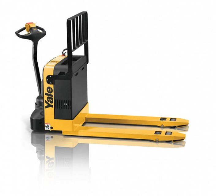
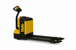
Yale Material Handling Corporation Pallet Truck MPW060
Need answers fast?
Explore the manual using AI.
Turn manuals into instant answers
with your AI-powered assistantTurn manuals into instant answers
with your AI-powered assistant
Manual for Yale Material Handling Corporation Pallet Truck MPW060
Complete asset maintenance, one click away
Get instant access to all the maintenance information you need. Empower technicians to perform preventive maintenance with asset packages, ready to use right out of the box.

Documents & Manuals
Find all the essential guides in one place.
 Tensioning Guide
- Belt-diagram
- C-120 pulleys
+ 13 more

Work Order Templates
Pre-built workflows to keep your asset running smoothly.
- Daily Electrical System Inspection
- Replace Roller and Pulley
- Install Engine B-120
+ 29 more

Procedures
Integrate maintenance plans directly into your work orders.
- Motion Industries
- Applied Industrial Technologies
- Electrical Brothers
+ 5 more

Parts
Access the parts list for your equipment in MaintainX.
- Drive Motor
- B2 Rollers
- Tensioning System
+ 40 more
Yale Material Handling Corporation Pallet Truck MPW060
Create an account to install this asset package.
Maintenance Plans for Yale Material Handling Corporation Pallet Truck Model MPW060
Integrate maintenance plans directly into your work orders in MaintainX.
Contactor Component Replacement
NOTE: If both the contacts and the coil of a contactor need to be replaced, replace the complete contactor as described above. Replace all of the contacts for any contactor if any contact needs replacing.
Contactor removed as described in CONTACTOR REPLACEMENT.
Identification of the buss bars for correct installation.
Buss bars and nuts that fasten to the fixed contacts removed.
Two screws that fasten the cover to the contactor removed.
Cover of the contactor removed without losing the plunger springs.
Four fixed contacts in the contactor cover replaced.
Two plunger assemblies and movable contacts removed and three fixed contact bars replaced.
Contacts of the plungers replaced.

Hydraulic Pump Motor-Brush Replacement
Move key to OFF position and disconnect the battery
WARNING: The capacitor in the motor controller can hold an electrical charge after the battery is disconnected. To prevent electrical shock and injury, discharge the capacitor before inspecting or repairing any component in the drive unit compartment. Wear safety glasses. Make certain the battery has been disconnected.
Use a screwdriver or jumper wire to make a short-circuit across the B+ and B-terminals of the motor controller
Loosen the two capscrews retaining the hydraulic unit to the frame and tip the hydraulic unit toward the front of the lift truck
Remove the two capscrews retaining the cover to the motor and remove the cover
Remove the springs and brushes
Measure the brushes. The brushes should be a minimum of 7 mm (0.275 in) in length at the smallest point
Replace the brushes as a set and inspect the springs for damage from heat (color changes) and corrosion. Replace any damaged springs
Install the cover and the two capscrews to retain the cover
Fork Height Adjustment
CAUTION: Improper adjustment of the fork height can cause excessive wear to one of the load wheels and poor pallet entry and exit.
Lower the forks completely (the cylinder should be bottomed out).
On early production models, remove the four capscrews retaining the access covers on each fork. Late production models do not have an access cover.
Loosen the nuts on the pull rod on each side of the pull rod yoke.
Ensure that load wheel supports are completely lowered. Check that the top of the load wheel support is flush with the underside of the fork weldment.
Adjust the rear fork height adjustment screws on each side, with the battery in place, to obtain a fork height of 85.9 to 88.9 mm (3.38to 3.5 in) at the rear of the forks.
Adjust both outer jam nuts and adjust the inner jam nuts to obtain a fork height (measured at the front of the forks) of 82.5 to 84.1 (3.25 to 3.31 in).
Ensure that the measurements are the same on each side and that the forks lift at the same time.
After the adjustments have been made, tighten the jam nut(s)to 176 N«m (130 Ibf ft) torque.
Brush and Comutator Inspection
WARNING: Put blocks under each side of the truck under the drive unit frame. Position blocks on both sides of the load wheels. The blocks must prevent the lift truck from falling and causing injury or damage.
Raise the drive wheel off the floor. Block the lift truck. See Section 1-HOW TO PUT A LIFT TRUCK ON BLOCKS. Disconnect the battery.
Remove the drive unit compartment cover. Refer to Section 2-DRIVE UNIT COMPARTMENT COVER-REMOVAL AND INSTALLATION.
WARNING: The capacitor in the motor controller can hold an electrical charge after the battery is disconnected. To prevent electrical shock and injury, discharge the capacitor before inspecting or repairing any component in the drive unit compartment. Wear safety glasses. Make certain the battery has been disconnected.
Discharge the capacitor in the motor controller.
If used, remove the brush covers to the motor. Wear eye protection. Use a vacuum cleaner or compressed air to remove dirt and 'brush dust' from the commutator area.
Visually inspect the commutator surface. Refer to Figures 3-20 through 3-28. The commutator wears slowly in normal service. The mica must be cut below the surface of the commutator bars after a long service period or after a commutator has been turned in a lathe. Carefully rotate the armature. DO NOT damage the commutator if you use a tool to rotate the armature.
Inspect the white or gray insulation (mica) between the commutator bars. The mica must not touch the brushes or the brushes will wear very rapidly.
Install the brush covers, when used and the drive unit compartment cover. Refer to Section 2-DRIVE UNIT COMPARTMENT-REMOVAL AND INSTALLATION.
Fuses Replacement
WARNING: The capacitor in the motor controller can hold an electrical charge after the battery is disconnected. To prevent electrical shock and injury, discharge the capacitor before inspecting or repairing any component in the drive unit compartment. Wear safety glasses. Make certain the battery has been disconnected. Use a screwdriver or jumper wire to make a short-circuit across the B+ and B-terminals of the motor controller.
Safety glasses worn
Battery disconnected
Capacitor discharged
Motorized hand trucks use a single 15 amp fuse for the control circuit, and 200 amp fuses for both the hydraulic pump motor and the drive motor. The fuses are located on the contactor panel.
15 amp fuse for the control circuit checked
200 amp fuse for the hydraulic pump motor checked
200 amp fuse for the drive motor checked
Remove and replace as required. If it cannot be determined visually that a fuse has failed, check for continuity using an ohmmeter.
Parts for Yale Material Handling Corporation Pallet Truck MPW060
Access the parts list for your equipment in MaintainX.
Operational Maintenance Manual
5192938-04
Hydraulic Oil, Normal Storage
5143618-00
Hydraulic Oil, Cold Storage
0034142-00
Hydraulic Oil, Arctic Storage
0032570-00
Gear Oil, 80W-90
3101530-34
Operational Maintenance Manual
5192938-04
Hydraulic Oil, Normal Storage
5143618-00
Hydraulic Oil, Cold Storage
0034142-00
Hydraulic Oil, Arctic Storage
0032570-00
Gear Oil, 80W-90
3101530-34
Operational Maintenance Manual
5192938-04
Hydraulic Oil, Normal Storage
5143618-00
Hydraulic Oil, Cold Storage
0034142-00
Hydraulic Oil, Arctic Storage
0032570-00
Gear Oil, 80W-90
3101530-34
Unlock efficiency
with MaintainX CoPilot
MaintainX CoPilot is your expert colleague, on call 24/7, helping your team find the answers they need to keep equipment running.
Reduce Unplanned Downtime
Ensure your team follows consistent procedures to minimize equipment failures and costly delays.
Maximize Asset Availability
Keep your assets running longer and more reliably, with standardized maintenance workflows from OEM manuals.
Lower Maintenance Costs
Turn any technician into an expert to streamline operations, maintain more assets, and reduce overall costs.
Thousands of companies manage their assets with MaintainX

'%3e%3cpath%20fill='url(%23b)'%20d='M66.008%2080.068c-5.084-.786-9.763-3.834-12.442-8.68a16.942%2016.942%200%200%201-1.87-5.18c1.096.19%202.203.476%203.298.87%206.525%202.333%2010.836%207.68%2011.014%2012.99ZM51.47%2061.576c.488-5.524%203.62-10.716%208.847-13.597a17.132%2017.132%200%200%201%2011.335-1.882c-.798%208.145-7.43%2014.848-16.038%2015.599-1.417.119-2.799.07-4.144-.12Zm28.564-11.478a17.513%2017.513%200%200%201%203.727%204.62c4.608%208.335%201.584%2018.813-6.75%2023.409a16.988%2016.988%200%200%201-4.359%201.679%2019.624%2019.624%200%200%201-3.977-12.776c.346-7.561%204.942-13.931%2011.36-16.932Z'/%3e%3cpath%20fill='%23110F0D'%20fill-rule='evenodd'%20d='M142.831%2048.324h4.977V77.03h-4.977V48.324Zm27.278%2013.002c.322%201.048.453%202.263.453%203.62v12.073h-4.787V66.208c0-.75-.047-1.572-.154-2.143-.453-2.382-1.822-3.572-4.215-3.572-2.31%200-3.882%201.274-4.43%203.476-.143.596-.226%201.405-.226%202.25v10.8h-4.787V56.623h4.477v2.989c1.536-2.5%203.906-3.43%206.371-3.43%203.488%200%206.263%201.68%207.298%205.144Zm24.636%207.323c0%203.882-2.358%206.525-5.763%207.727-1.298.453-2.632.643-4.62.643h-10.169V48.324h9.085c1.691%200%203.156.143%204.049.38%203.465.93%205.727%203.68%205.727%207.335%200%202.441-.81%204.156-2.762%205.644%202.905%201.417%204.453%203.727%204.453%206.966Zm-15.634-8.656h4.584c1.024%200%201.917-.143%202.536-.417%201.215-.548%201.905-1.608%201.905-3.167%200-1.548-.643-2.572-1.845-3.132-.691-.31-1.762-.452-2.763-.452h-4.417v7.168Zm10.716%208.465c0-1.536-.893-3.37-3.227-3.893-.428-.095-1.036-.143-1.571-.143h-5.918v8.085h5.501c.56%200%201.429-.048%201.953-.167%201.94-.453%203.262-1.846%203.262-3.882Zm47.747-11.847-8.097%2020.408h-4.429l-8.109-20.408h5.191l5.192%2014.574%205.108-14.574h5.144Zm-20.218%2010.002c0%20.69-.036%201.262-.155%201.94h-15.943c.631%202.87%202.714%204.728%205.882%204.728%202.131%200%203.607-.882%204.703-2.525h4.87c-1.762%204.144-5.204%206.692-9.657%206.692-6.084%200-10.537-4.858-10.537-10.49%200-6.108%204.524-10.776%2010.335-10.776%206.239%200%2010.442%204.954%2010.502%2010.43Zm-4.763-1.405c-.333-2.846-2.643-4.858-5.691-4.858-2.894%200-5.287%201.929-5.621%204.858h11.312Zm-72.667%203.44c0%204.787-3.287%208.371-9.419%208.371H119.363V64.66c-1.917.274-3.87.69-5.811%201.238l4.537%2011.121h-5.418l-3.596-9.585c-5.144%202.084-10.085%205.216-14.217%209.585h-4.786L101.8%2048.312h4.56l5.68%2013.883a44.112%2044.112%200%200%201%207.323-1.774V48.312h9.084c1.703%200%203.156.143%204.061.393%203.453.929%205.727%203.667%205.727%207.323%200%201.917-.738%204.179-2.81%205.691%203.06%201.56%204.501%204.025%204.501%206.93Zm-15.634-8.667a62.664%2062.664%200%200%201%202.06-.036c1.703.012%203.239.131%204.608.37%201.441-.549%202.357-1.727%202.357-3.537%200-1.941-.881-3.144-2.488-3.667-.548-.18-1.358-.286-2.322-.286h-4.215v7.156Zm-16.55%203.905-3.715-9.894-6.394%2016.502c2.833-2.595%206.263-4.858%2010.109-6.608Zm27.254%204.74c0-2.775-3.131-4.347-8.513-4.418-.715%200-1.441.011-2.191.047v8.252h5.918c2.548%200%204.786-1.37%204.786-3.882Z'%20clip-rule='evenodd'/%3e%3c/g%3e%3cdefs%3e%3clinearGradient%20id='b'%20x1='51.47'%20x2='85.916'%20y1='62.946'%20y2='62.946'%20gradientUnits='userSpaceOnUse'%3e%3cstop%20stop-color='%23CD9F28'/%3e%3cstop%20offset='1'%20stop-color='%23ECD80B'/%3e%3c/linearGradient%3e%3cclipPath%20id='a'%3e%3cpath%20fill='%23fff'%20d='M51.47%2045.728h186.104V80.14H51.47z'/%3e%3c/clipPath%3e%3c/defs%3e%3c/svg%3e)


More from Yale Material Handling Corporation


Explore Other Assets


© 2026 MaintainX. All rights reserved.