


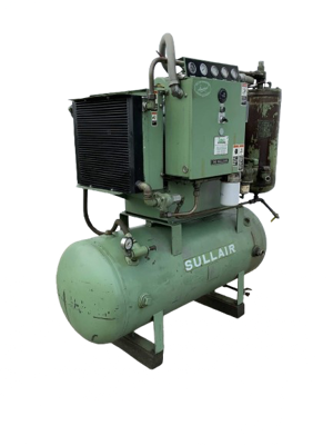
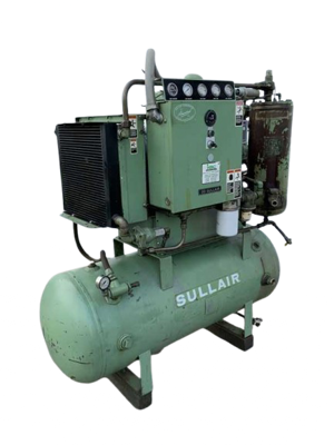
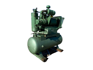
Sullair Water-Cooled Compressor 10B 40HP-251331-003 WC
Need answers fast?
Explore the manual using AI.
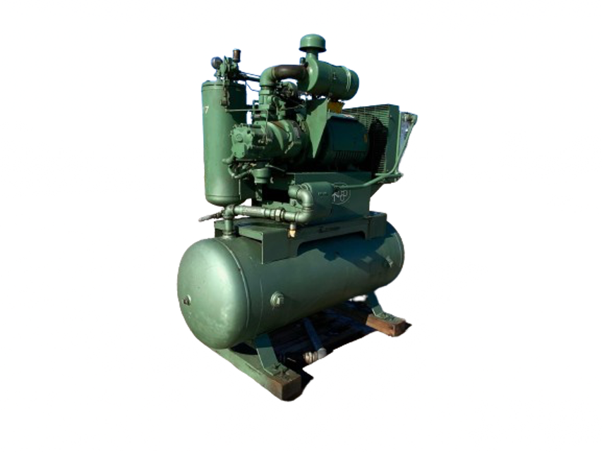
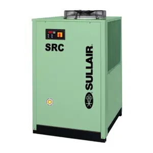
The Sullair Water-Cooled Compressor 10B 40HP-251331-003 WC is a robust industrial compressor designed for efficient cooling and air compression. Known for its reliability and performance, this model is ideal for various applications in manufacturing and processing industries.
Turn manuals into instant answers
with your AI-powered assistantTurn manuals into instant answers
with your AI-powered assistant
Complete asset maintenance, one click away
Get instant access to all the maintenance information you need. Empower technicians to perform preventive maintenance with asset packages, ready to use right out of the box.

Documents & Manuals
Find all the essential guides in one place.
 Tensioning Guide
- Belt-diagram
- C-120 pulleys
+ 13 more

Work Order Templates
Pre-built workflows to keep your asset running smoothly.
- Daily Electrical System Inspection
- Replace Roller and Pulley
- Install Engine B-120
+ 29 more

Procedures
Integrate maintenance plans directly into your work orders.
- Motion Industries
- Applied Industrial Technologies
- Electrical Brothers
+ 5 more

Parts
Access the parts list for your equipment in MaintainX.
- Drive Motor
- B2 Rollers
- Tensioning System
+ 40 more
Sullair Water-Cooled Compressor 10B 40HP-251331-003 WC
Create an account to install this asset package.
Maintenance Plans for Sullair Water-Cooled Compressor Model 10B 40HP-251331-003 WC
Integrate maintenance plans directly into your work orders in MaintainX.
Compressor Blowdown Valve Maintenance
Warning: Always ensure the compressor is turned off and fully depressurized before starting maintenance.
Replace o-rings and the teflon seat of Blow down valve no.250025-655. Use repair kit no. 250031-772.
Unscrew end caps from the valve body and remove
Hold nut with an appropriate socket wrench and turn screw until loose
Remove all internal parts mounted on the machine screw. Remove the old o-rings and teflon seat and discard
Replace with the new o-rings and teflon seat provided in the repair kit. Apply appropriate lubricant to o-rings and valve body bore
Pre-assemble the internal parts for pilot (P) side of the valve onto the screw and install into the body
Assemble remaining internal parts for inlet (I) side to the screw as illustrated. Once assembled, install the locknut and torque to 25 in.-lbs. (2.82Nm)
Screw end caps into the valve body until tight

Compressor Thermal Valve Maintenance
Warning: This maintenance check requires trained personnel with PPE!
Remove the appropriate piping from the thermal valve housing
Remove the four (4) capscrews holding the housing together and separate the upper housing from the lower housing
Remove element
Remove and replace the element seal in the upper housing
Remove and replace the o-ring between the upper and lower housings
Replace element
Re-assemble the housing
Sign off on the compressor thermal valve maintenance
1 Daily Compressor Maintenance
Check the fluid level in the sump. Should the level be low, simply add the necessary amount
Observe the gauges and indicators to be sure they monitor the correct readings for that particular phase of operation
Check on the overall compressor and gauges to assure that the compressor is running properly after it has warmed up
Clean the return line strainer after the initial 50 hours of operation
Clean the return line orifice after the initial 50 hours of operation
Compressor Minimum Pressure/ Check Valve Maintenance
WARNING: Before performing maintenance on the valve, be sure that all pressure has been relieved in the compressor sump, and all downstream pressure has been vented to the atmosphere. Also be sure that the components of the compressor are cool to the touch
All pressure relieved in the compressor sump?
All downstream pressure vented to the atmosphere?
Components of the compressor are cool to the touch?
Unscrew the minimum pressure/check valve (P/N 241581) from the receiver cover
Remove the hexagonal retaining cap from the main body
Remove the flat washer and heavy spring from the main body
Tap the piston assembly (with a screwdriver) from the bottom of the main body and remove. The o-ring will now be seen easily
Remove the seal ring and discard
1 Yearly Separator Replacement
Warning: This procedure requires trained personnel with PPE!
Choose the type of compressor
Pressure relieved from the sump tank and all compressor lines?
All piping connected to the sump cover disconnected?
Hex head capscrews from the cover plate loosened and removed?
Cover plate lifted from the sump?
Separator element removed?
Old gasket material scraped from the cover and flange on the sump?
New gaskets installed?
Parts for Sullair Water-Cooled Compressor 10B 40HP-251331-003 WC
Access the parts list for your equipment in MaintainX.
Fluid
046850–001
Check Valve
049905
Repair Kit
250019–453
Fluid
250022–669
Repair Kit
250034–114
Fluid
046850–001
Check Valve
049905
Repair Kit
250019–453
Fluid
250022–669
Repair Kit
250034–114
Fluid
046850–001
Check Valve
049905
Repair Kit
250019–453
Fluid
250022–669
Repair Kit
250034–114
Unlock efficiency
with MaintainX CoPilot
MaintainX CoPilot is your expert colleague, on call 24/7, helping your team find the answers they need to keep equipment running.
Reduce Unplanned Downtime
Ensure your team follows consistent procedures to minimize equipment failures and costly delays.
Maximize Asset Availability
Keep your assets running longer and more reliably, with standardized maintenance workflows from OEM manuals.
Lower Maintenance Costs
Turn any technician into an expert to streamline operations, maintain more assets, and reduce overall costs.
Thousands of companies manage their assets with MaintainX

'%3e%3cpath%20fill='url(%23b)'%20d='M66.008%2080.068c-5.084-.786-9.763-3.834-12.442-8.68a16.942%2016.942%200%200%201-1.87-5.18c1.096.19%202.203.476%203.298.87%206.525%202.333%2010.836%207.68%2011.014%2012.99ZM51.47%2061.576c.488-5.524%203.62-10.716%208.847-13.597a17.132%2017.132%200%200%201%2011.335-1.882c-.798%208.145-7.43%2014.848-16.038%2015.599-1.417.119-2.799.07-4.144-.12Zm28.564-11.478a17.513%2017.513%200%200%201%203.727%204.62c4.608%208.335%201.584%2018.813-6.75%2023.409a16.988%2016.988%200%200%201-4.359%201.679%2019.624%2019.624%200%200%201-3.977-12.776c.346-7.561%204.942-13.931%2011.36-16.932Z'/%3e%3cpath%20fill='%23110F0D'%20fill-rule='evenodd'%20d='M142.831%2048.324h4.977V77.03h-4.977V48.324Zm27.278%2013.002c.322%201.048.453%202.263.453%203.62v12.073h-4.787V66.208c0-.75-.047-1.572-.154-2.143-.453-2.382-1.822-3.572-4.215-3.572-2.31%200-3.882%201.274-4.43%203.476-.143.596-.226%201.405-.226%202.25v10.8h-4.787V56.623h4.477v2.989c1.536-2.5%203.906-3.43%206.371-3.43%203.488%200%206.263%201.68%207.298%205.144Zm24.636%207.323c0%203.882-2.358%206.525-5.763%207.727-1.298.453-2.632.643-4.62.643h-10.169V48.324h9.085c1.691%200%203.156.143%204.049.38%203.465.93%205.727%203.68%205.727%207.335%200%202.441-.81%204.156-2.762%205.644%202.905%201.417%204.453%203.727%204.453%206.966Zm-15.634-8.656h4.584c1.024%200%201.917-.143%202.536-.417%201.215-.548%201.905-1.608%201.905-3.167%200-1.548-.643-2.572-1.845-3.132-.691-.31-1.762-.452-2.763-.452h-4.417v7.168Zm10.716%208.465c0-1.536-.893-3.37-3.227-3.893-.428-.095-1.036-.143-1.571-.143h-5.918v8.085h5.501c.56%200%201.429-.048%201.953-.167%201.94-.453%203.262-1.846%203.262-3.882Zm47.747-11.847-8.097%2020.408h-4.429l-8.109-20.408h5.191l5.192%2014.574%205.108-14.574h5.144Zm-20.218%2010.002c0%20.69-.036%201.262-.155%201.94h-15.943c.631%202.87%202.714%204.728%205.882%204.728%202.131%200%203.607-.882%204.703-2.525h4.87c-1.762%204.144-5.204%206.692-9.657%206.692-6.084%200-10.537-4.858-10.537-10.49%200-6.108%204.524-10.776%2010.335-10.776%206.239%200%2010.442%204.954%2010.502%2010.43Zm-4.763-1.405c-.333-2.846-2.643-4.858-5.691-4.858-2.894%200-5.287%201.929-5.621%204.858h11.312Zm-72.667%203.44c0%204.787-3.287%208.371-9.419%208.371H119.363V64.66c-1.917.274-3.87.69-5.811%201.238l4.537%2011.121h-5.418l-3.596-9.585c-5.144%202.084-10.085%205.216-14.217%209.585h-4.786L101.8%2048.312h4.56l5.68%2013.883a44.112%2044.112%200%200%201%207.323-1.774V48.312h9.084c1.703%200%203.156.143%204.061.393%203.453.929%205.727%203.667%205.727%207.323%200%201.917-.738%204.179-2.81%205.691%203.06%201.56%204.501%204.025%204.501%206.93Zm-15.634-8.667a62.664%2062.664%200%200%201%202.06-.036c1.703.012%203.239.131%204.608.37%201.441-.549%202.357-1.727%202.357-3.537%200-1.941-.881-3.144-2.488-3.667-.548-.18-1.358-.286-2.322-.286h-4.215v7.156Zm-16.55%203.905-3.715-9.894-6.394%2016.502c2.833-2.595%206.263-4.858%2010.109-6.608Zm27.254%204.74c0-2.775-3.131-4.347-8.513-4.418-.715%200-1.441.011-2.191.047v8.252h5.918c2.548%200%204.786-1.37%204.786-3.882Z'%20clip-rule='evenodd'/%3e%3c/g%3e%3cdefs%3e%3clinearGradient%20id='b'%20x1='51.47'%20x2='85.916'%20y1='62.946'%20y2='62.946'%20gradientUnits='userSpaceOnUse'%3e%3cstop%20stop-color='%23CD9F28'/%3e%3cstop%20offset='1'%20stop-color='%23ECD80B'/%3e%3c/linearGradient%3e%3cclipPath%20id='a'%3e%3cpath%20fill='%23fff'%20d='M51.47%2045.728h186.104V80.14H51.47z'/%3e%3c/clipPath%3e%3c/defs%3e%3c/svg%3e)


More from Sullair


Explore Other Assets


© 2026 MaintainX. All rights reserved.