


Sullair Industrial Air Compressor 1809V AC
Need answers fast?
Explore the manual using AI.
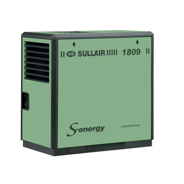
The Sullair Industrial Air Compressor 1809V AC is a robust and efficient solution for various industrial applications. Known for its reliability and performance, this model ensures optimal air delivery while minimizing downtime and maintenance costs. Ideal for heavy-duty use, it is designed to meet the demands of modern manufacturing environments.
Turn manuals into instant answers
with your AI-powered assistantTurn manuals into instant answers
with your AI-powered assistant
Manual for Sullair Industrial Air Compressor 1809V AC
Complete asset maintenance, one click away
Get instant access to all the maintenance information you need. Empower technicians to perform preventive maintenance with asset packages, ready to use right out of the box.

Documents & Manuals
Find all the essential guides in one place.
 Tensioning Guide
- Belt-diagram
- C-120 pulleys
+ 13 more

Work Order Templates
Pre-built workflows to keep your asset running smoothly.
- Daily Electrical System Inspection
- Replace Roller and Pulley
- Install Engine B-120
+ 29 more

Procedures
Integrate maintenance plans directly into your work orders.
- Motion Industries
- Applied Industrial Technologies
- Electrical Brothers
+ 5 more

Parts
Access the parts list for your equipment in MaintainX.
- Drive Motor
- B2 Rollers
- Tensioning System
+ 40 more
Sullair Industrial Air Compressor 1809V AC
Create an account to install this asset package.
Maintenance Plans for Sullair Industrial Air Compressor Model 1809V AC
Integrate maintenance plans directly into your work orders in MaintainX.
Pressure Regulator Adjustment
Warning: This procedure requires trained personnel with PPE!
Is the compressor started?
Enter the service air pressure
Is the service air pressure approximately 1 psi over rated pressure?
Did you turn the inlet valve regulator adjusting screw until air just begins to escape from the control air orifice?
Did you lock the adjusting screw in place with the locknut?
Is the regulator now properly set?
Sign off on the pressure regulator adjustment

Shaft Coupling Maintenance
The compressor unit and motor are rigidly connected via a mounting adapter housing.
This arrangement makes coupling alignment unnecessary.
The coupling is a jaw type in shear. If the elastomeric element requires replacement due to wear or breakage, order replacement element no. 02250152-669, and follow the following steps:
1. Remove the protective grill from the adapter housing.
2. Loosen the retaining screw located on the outer sleeve. Slide the sleeve to one side, exposing the coupling element.
3. Unwrap the coupling element from the coupling jaws.
4. Install the new element by wrapping it around the jaws, engaging the cogs on the element into the jaws.
5. Reinstall the outer sleeve and torque the securing screws to 10 in·lb (1.13 N·m). Install the protective grill.;
1 Daily Compressor Inspection
Warning: HIGH-PRESSURE HAZARD! DO NOT remove caps, plugs, and/or other components when compressor is running or pressurized. Stop compressor and relieve all internal pressure before doing so. Failure to comply could result in death or serious injury.
Fluid level in the separator/sump tank is sufficient
If fluid level is low, enter the amount of fluid added
Is the addition of fluid becoming too frequent?
If the addition of fluid becomes too frequent, refer to Section 6.9: Troubleshooting—Introduction on page 61 under EXCESSIVE COMPRESSOR FLUID CONSUMPTION for a probable cause and remedy.
Controller display monitors the correct readings for their particular phase of operation
Compressor is running properly after warming up
Sign off on the daily compressor inspection
1 Yearly Control Line Strainer Cleaning
Warning: This procedure requires trained personnel with PPE!
Regulator and solenoid valve(s) are protected by a strainer?
If not, report the issue to the maintenance team and stop the procedure
Hex cap from the strainer removed?
Strainer screen removed?
Screen cleaned?
Is the screen damaged?
If the screen is damaged, the strainer assembly must be replaced (P/N 241772)
Sign off on the strainer cleaning
2000 Hourly Fluid Return/Sight Glass Maintenance
The fluid return/sight glass subassembly is attached to the side of the separator tank.
Fluid return/sight glass maintenance should be performed on a routine basis parallel to that of the fluid filter, or as indicated in Section 6.9: Troubleshooting—Introduction on page 63.
The maintenance on a fluid return/sight glass is mainly concerned with the condition of the filter assembly. Order filter assembly No. 02250117-782, and use the following instructions as a guide.
1. Disconnect the tube at the bottom of the sight glass.
2. Unscrew the sight glass assembly where the elbow fitting joins the strainer/filter.
3. Remove used filter assembly, and replace with new assembly.
4. Inspect and clean the orifice inside the sight glass blocks. The orifice must be removed with an Allen wrench.
5. Coat/lubricate the O-rings with silicone grease.
6. Reattach the connectors to the sight glass/orifice blocks.;
Parts for Sullair Industrial Air Compressor 1809V AC
Access the parts list for your equipment in MaintainX.
Valve, Check 1/4”-NPT
02250115-272
Valve, 1-5/8 SAE Min Press Check
02250097-609
Valve, Thermal 195 DEG
02250092-081
Transducer, Pressure 0-250PSI 1-5VDC N4
02250155-174
Valve, Relief 1/2” 200#
250006-938
Valve, Check 1/4”-NPT
02250115-272
Valve, 1-5/8 SAE Min Press Check
02250097-609
Valve, Thermal 195 DEG
02250092-081
Transducer, Pressure 0-250PSI 1-5VDC N4
02250155-174
Valve, Relief 1/2” 200#
250006-938
Valve, Check 1/4”-NPT
02250115-272
Valve, 1-5/8 SAE Min Press Check
02250097-609
Valve, Thermal 195 DEG
02250092-081
Transducer, Pressure 0-250PSI 1-5VDC N4
02250155-174
Valve, Relief 1/2” 200#
250006-938
Unlock efficiency
with MaintainX CoPilot
MaintainX CoPilot is your expert colleague, on call 24/7, helping your team find the answers they need to keep equipment running.
Reduce Unplanned Downtime
Ensure your team follows consistent procedures to minimize equipment failures and costly delays.
Maximize Asset Availability
Keep your assets running longer and more reliably, with standardized maintenance workflows from OEM manuals.
Lower Maintenance Costs
Turn any technician into an expert to streamline operations, maintain more assets, and reduce overall costs.
Thousands of companies manage their assets with MaintainX

'%3e%3cpath%20fill='url(%23b)'%20d='M66.008%2080.068c-5.084-.786-9.763-3.834-12.442-8.68a16.942%2016.942%200%200%201-1.87-5.18c1.096.19%202.203.476%203.298.87%206.525%202.333%2010.836%207.68%2011.014%2012.99ZM51.47%2061.576c.488-5.524%203.62-10.716%208.847-13.597a17.132%2017.132%200%200%201%2011.335-1.882c-.798%208.145-7.43%2014.848-16.038%2015.599-1.417.119-2.799.07-4.144-.12Zm28.564-11.478a17.513%2017.513%200%200%201%203.727%204.62c4.608%208.335%201.584%2018.813-6.75%2023.409a16.988%2016.988%200%200%201-4.359%201.679%2019.624%2019.624%200%200%201-3.977-12.776c.346-7.561%204.942-13.931%2011.36-16.932Z'/%3e%3cpath%20fill='%23110F0D'%20fill-rule='evenodd'%20d='M142.831%2048.324h4.977V77.03h-4.977V48.324Zm27.278%2013.002c.322%201.048.453%202.263.453%203.62v12.073h-4.787V66.208c0-.75-.047-1.572-.154-2.143-.453-2.382-1.822-3.572-4.215-3.572-2.31%200-3.882%201.274-4.43%203.476-.143.596-.226%201.405-.226%202.25v10.8h-4.787V56.623h4.477v2.989c1.536-2.5%203.906-3.43%206.371-3.43%203.488%200%206.263%201.68%207.298%205.144Zm24.636%207.323c0%203.882-2.358%206.525-5.763%207.727-1.298.453-2.632.643-4.62.643h-10.169V48.324h9.085c1.691%200%203.156.143%204.049.38%203.465.93%205.727%203.68%205.727%207.335%200%202.441-.81%204.156-2.762%205.644%202.905%201.417%204.453%203.727%204.453%206.966Zm-15.634-8.656h4.584c1.024%200%201.917-.143%202.536-.417%201.215-.548%201.905-1.608%201.905-3.167%200-1.548-.643-2.572-1.845-3.132-.691-.31-1.762-.452-2.763-.452h-4.417v7.168Zm10.716%208.465c0-1.536-.893-3.37-3.227-3.893-.428-.095-1.036-.143-1.571-.143h-5.918v8.085h5.501c.56%200%201.429-.048%201.953-.167%201.94-.453%203.262-1.846%203.262-3.882Zm47.747-11.847-8.097%2020.408h-4.429l-8.109-20.408h5.191l5.192%2014.574%205.108-14.574h5.144Zm-20.218%2010.002c0%20.69-.036%201.262-.155%201.94h-15.943c.631%202.87%202.714%204.728%205.882%204.728%202.131%200%203.607-.882%204.703-2.525h4.87c-1.762%204.144-5.204%206.692-9.657%206.692-6.084%200-10.537-4.858-10.537-10.49%200-6.108%204.524-10.776%2010.335-10.776%206.239%200%2010.442%204.954%2010.502%2010.43Zm-4.763-1.405c-.333-2.846-2.643-4.858-5.691-4.858-2.894%200-5.287%201.929-5.621%204.858h11.312Zm-72.667%203.44c0%204.787-3.287%208.371-9.419%208.371H119.363V64.66c-1.917.274-3.87.69-5.811%201.238l4.537%2011.121h-5.418l-3.596-9.585c-5.144%202.084-10.085%205.216-14.217%209.585h-4.786L101.8%2048.312h4.56l5.68%2013.883a44.112%2044.112%200%200%201%207.323-1.774V48.312h9.084c1.703%200%203.156.143%204.061.393%203.453.929%205.727%203.667%205.727%207.323%200%201.917-.738%204.179-2.81%205.691%203.06%201.56%204.501%204.025%204.501%206.93Zm-15.634-8.667a62.664%2062.664%200%200%201%202.06-.036c1.703.012%203.239.131%204.608.37%201.441-.549%202.357-1.727%202.357-3.537%200-1.941-.881-3.144-2.488-3.667-.548-.18-1.358-.286-2.322-.286h-4.215v7.156Zm-16.55%203.905-3.715-9.894-6.394%2016.502c2.833-2.595%206.263-4.858%2010.109-6.608Zm27.254%204.74c0-2.775-3.131-4.347-8.513-4.418-.715%200-1.441.011-2.191.047v8.252h5.918c2.548%200%204.786-1.37%204.786-3.882Z'%20clip-rule='evenodd'/%3e%3c/g%3e%3cdefs%3e%3clinearGradient%20id='b'%20x1='51.47'%20x2='85.916'%20y1='62.946'%20y2='62.946'%20gradientUnits='userSpaceOnUse'%3e%3cstop%20stop-color='%23CD9F28'/%3e%3cstop%20offset='1'%20stop-color='%23ECD80B'/%3e%3c/linearGradient%3e%3cclipPath%20id='a'%3e%3cpath%20fill='%23fff'%20d='M51.47%2045.728h186.104V80.14H51.47z'/%3e%3c/clipPath%3e%3c/defs%3e%3c/svg%3e)


More from Sullair


Explore Other Assets


© 2026 MaintainX. All rights reserved.