


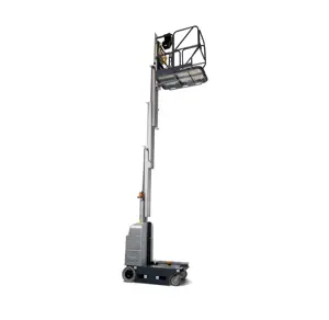
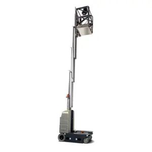
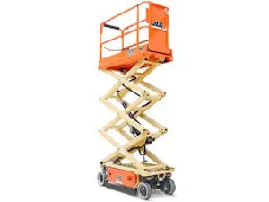
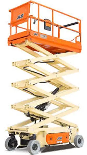
JLG Driveable Stock Picker 20MSP
Need answers fast?
Explore the manual using AI.

Turn manuals into instant answers
with your AI-powered assistantTurn manuals into instant answers
with your AI-powered assistant
Complete asset maintenance, one click away
Get instant access to all the maintenance information you need. Empower technicians to perform preventive maintenance with asset packages, ready to use right out of the box.

Documents & Manuals
Find all the essential guides in one place.
 Tensioning Guide
- Belt-diagram
- C-120 pulleys
+ 13 more

Work Order Templates
Pre-built workflows to keep your asset running smoothly.
- Daily Electrical System Inspection
- Replace Roller and Pulley
- Install Engine B-120
+ 29 more

Procedures
Integrate maintenance plans directly into your work orders.
- Motion Industries
- Applied Industrial Technologies
- Electrical Brothers
+ 5 more

Parts
Access the parts list for your equipment in MaintainX.
- Drive Motor
- B2 Rollers
- Tensioning System
+ 40 more
JLG Driveable Stock Picker 20MSP
Create an account to install this asset package.
Maintenance Plans for JLG Driveable Stock Picker Model 20MSP
Integrate maintenance plans directly into your work orders in MaintainX.
Drive Motor Brushes Replacement
Caution: THE MOTOR MUST BE DISASSEMBLED FROM THE GEARBOX AND DISCONNECTED FROM THE MACHINE CONTROLLER BEFORE BEGINNING THIS PROCEDURE. SEE WHEEL DRIVE ASSEMBLY - REMOVAL FROM MACHINE AND WHEEL DRIVE DISASSEMBLY - MAIN COMPONENTS ON THE PREVIOUS PAGES.
Wrap tape around the end of the motor shaft that interfaces with the gearbox to avoid damage to this area.
Remove the motor thru bolts.
Remove the motor flange/brake mount from the motor frame.
Remove the brush housing from the motor frame and armature by tapping the edge of the brush housing with a soft-tipped mallet. The brushes will spring towards the center of the brush housing once it has separated from the armature.
Remove the wave spring washer from the bearing bore of the brush housing and set aside.
Pick a brush and remove the screw that fastens its lead to the brush holder.
Remove the brush and brush spring.
Inspect the brush holder for corrosion. Remove any corrosion that is found.

Wheel Drive Assembly Roll Test
Warning: Ensure the brake is released before performing the roll test. This can be accomplished by supplying 24 Volts D.C. to the gray 2-pin brake connector.
Is the brake released?
Are the unit's gears rotating freely and properly?
Describe any inconsistencies or difficulties in gear rotation.
Are the gears rolling with consistency?
Describe any inconsistencies in gear rolling.
Sign off on the wheel drive assembly roll test.
Bearings Maintenance
Warning: Always cover the bearing when removed to keep out dirt and abrasives.
Cleaned bearings in nonflammable cleaning solvent and allowed to drip dry.
Used compressed air to dry the bearing without spinning it.
Discarded bearings if the races and balls (or rollers) are pitted, scored, or burned.
Applied a light coat of oil and wrapped it in clean (waxed) paper if bearing is found to be serviceable.
Do not unwrap reusable or new bearings until they are ready to install.
Lubricated new or used serviceable bearings before installation.
When pressing a bearing into a retainer or bore, applied pressure to the outer race.
If the bearing is to be installed on a shaft, applied pressure to the inner race.
1 Yearly Driveable Stock Picker Maintenance
Mast Assembly:
- Mast Sections: Visual inspection for damage, cracks, distortion, or excessive wear. Operates properly.
- Chain Systems: Properly lubricated. Inspected per Service and Maintenance Manual.
- Sequence Cable Systems: Check for proper and secure installation. Visual inspection for damage, cracks, distortion, or excessive wear. Check for proper adjustment.
- Covers or Shields: Check for proper and secure installation.
- Sheave Systems: Check for proper and secure installation. Visual inspection for damage, cracks, distortion, or excessive wear.
- Bearings: Check for proper and secure installation. Visual inspection for damage, cracks, distortion, or excessive wear.
- Slide Pads: Check for proper and secure installation. Visual inspection for damage, cracks, distortion, or excessive wear.
Platform Assembly:
Transducer Sensor Check
Power up machine by setting the Power Selector (Key) Switch to Ground Control Mode
Raise the platform approximately four (4) to five (5) feet
Hold an object about the size of 8-1/2 x 11 inches directly under one of the sensors. The OSS Control Module (RED) LED will flash if the sensor is working properly
Remove object, allow the LED to stop flashing and check the next sensor
Number of sensors checked
Sign off on the transducer sensor check
Parts for JLG Driveable Stock Picker 20MSP
Access the parts list for your equipment in MaintainX.
Di-Electric Grease
3020038
Ground Control Station, For Removal Of Electrical Connector Pins From The Ground Control Station Connectors
7016618
Drive Motor, For Removal Of Electrical Connector Pins From The Drive Motor Main Power Connectors
7002841
Drive Motor, Brake For Removal Of Electrical Connector Pins From The Drive Motor Brake Power Connectors
7002842
Anerobic Thread Locking Compound, Medium Strength (Blue)
0100011
Unlock efficiency
with MaintainX CoPilot
MaintainX CoPilot is your expert colleague, on call 24/7, helping your team find the answers they need to keep equipment running.
Reduce Unplanned Downtime
Ensure your team follows consistent procedures to minimize equipment failures and costly delays.
Maximize Asset Availability
Keep your assets running longer and more reliably, with standardized maintenance workflows from OEM manuals.
Lower Maintenance Costs
Turn any technician into an expert to streamline operations, maintain more assets, and reduce overall costs.
Thousands of companies manage their assets with MaintainX

'%3e%3cpath%20fill='url(%23b)'%20d='M66.008%2080.068c-5.084-.786-9.763-3.834-12.442-8.68a16.942%2016.942%200%200%201-1.87-5.18c1.096.19%202.203.476%203.298.87%206.525%202.333%2010.836%207.68%2011.014%2012.99ZM51.47%2061.576c.488-5.524%203.62-10.716%208.847-13.597a17.132%2017.132%200%200%201%2011.335-1.882c-.798%208.145-7.43%2014.848-16.038%2015.599-1.417.119-2.799.07-4.144-.12Zm28.564-11.478a17.513%2017.513%200%200%201%203.727%204.62c4.608%208.335%201.584%2018.813-6.75%2023.409a16.988%2016.988%200%200%201-4.359%201.679%2019.624%2019.624%200%200%201-3.977-12.776c.346-7.561%204.942-13.931%2011.36-16.932Z'/%3e%3cpath%20fill='%23110F0D'%20fill-rule='evenodd'%20d='M142.831%2048.324h4.977V77.03h-4.977V48.324Zm27.278%2013.002c.322%201.048.453%202.263.453%203.62v12.073h-4.787V66.208c0-.75-.047-1.572-.154-2.143-.453-2.382-1.822-3.572-4.215-3.572-2.31%200-3.882%201.274-4.43%203.476-.143.596-.226%201.405-.226%202.25v10.8h-4.787V56.623h4.477v2.989c1.536-2.5%203.906-3.43%206.371-3.43%203.488%200%206.263%201.68%207.298%205.144Zm24.636%207.323c0%203.882-2.358%206.525-5.763%207.727-1.298.453-2.632.643-4.62.643h-10.169V48.324h9.085c1.691%200%203.156.143%204.049.38%203.465.93%205.727%203.68%205.727%207.335%200%202.441-.81%204.156-2.762%205.644%202.905%201.417%204.453%203.727%204.453%206.966Zm-15.634-8.656h4.584c1.024%200%201.917-.143%202.536-.417%201.215-.548%201.905-1.608%201.905-3.167%200-1.548-.643-2.572-1.845-3.132-.691-.31-1.762-.452-2.763-.452h-4.417v7.168Zm10.716%208.465c0-1.536-.893-3.37-3.227-3.893-.428-.095-1.036-.143-1.571-.143h-5.918v8.085h5.501c.56%200%201.429-.048%201.953-.167%201.94-.453%203.262-1.846%203.262-3.882Zm47.747-11.847-8.097%2020.408h-4.429l-8.109-20.408h5.191l5.192%2014.574%205.108-14.574h5.144Zm-20.218%2010.002c0%20.69-.036%201.262-.155%201.94h-15.943c.631%202.87%202.714%204.728%205.882%204.728%202.131%200%203.607-.882%204.703-2.525h4.87c-1.762%204.144-5.204%206.692-9.657%206.692-6.084%200-10.537-4.858-10.537-10.49%200-6.108%204.524-10.776%2010.335-10.776%206.239%200%2010.442%204.954%2010.502%2010.43Zm-4.763-1.405c-.333-2.846-2.643-4.858-5.691-4.858-2.894%200-5.287%201.929-5.621%204.858h11.312Zm-72.667%203.44c0%204.787-3.287%208.371-9.419%208.371H119.363V64.66c-1.917.274-3.87.69-5.811%201.238l4.537%2011.121h-5.418l-3.596-9.585c-5.144%202.084-10.085%205.216-14.217%209.585h-4.786L101.8%2048.312h4.56l5.68%2013.883a44.112%2044.112%200%200%201%207.323-1.774V48.312h9.084c1.703%200%203.156.143%204.061.393%203.453.929%205.727%203.667%205.727%207.323%200%201.917-.738%204.179-2.81%205.691%203.06%201.56%204.501%204.025%204.501%206.93Zm-15.634-8.667a62.664%2062.664%200%200%201%202.06-.036c1.703.012%203.239.131%204.608.37%201.441-.549%202.357-1.727%202.357-3.537%200-1.941-.881-3.144-2.488-3.667-.548-.18-1.358-.286-2.322-.286h-4.215v7.156Zm-16.55%203.905-3.715-9.894-6.394%2016.502c2.833-2.595%206.263-4.858%2010.109-6.608Zm27.254%204.74c0-2.775-3.131-4.347-8.513-4.418-.715%200-1.441.011-2.191.047v8.252h5.918c2.548%200%204.786-1.37%204.786-3.882Z'%20clip-rule='evenodd'/%3e%3c/g%3e%3cdefs%3e%3clinearGradient%20id='b'%20x1='51.47'%20x2='85.916'%20y1='62.946'%20y2='62.946'%20gradientUnits='userSpaceOnUse'%3e%3cstop%20stop-color='%23CD9F28'/%3e%3cstop%20offset='1'%20stop-color='%23ECD80B'/%3e%3c/linearGradient%3e%3cclipPath%20id='a'%3e%3cpath%20fill='%23fff'%20d='M51.47%2045.728h186.104V80.14H51.47z'/%3e%3c/clipPath%3e%3c/defs%3e%3c/svg%3e)


More from JLG

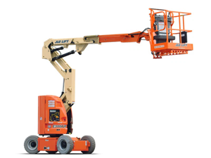
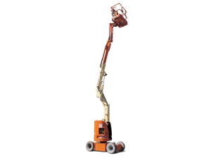
Explore Other Assets


© 2026 MaintainX. All rights reserved.