


Turn manuals into instant answers
with your AI-powered assistantTurn manuals into instant answers
with your AI-powered assistant
Complete asset maintenance, one click away
Get instant access to all the maintenance information you need. Empower technicians to perform preventive maintenance with asset packages, ready to use right out of the box.

Documents & Manuals
Find all the essential guides in one place.
 Tensioning Guide
- Belt-diagram
- C-120 pulleys
+ 13 more

Work Order Templates
Pre-built workflows to keep your asset running smoothly.
- Daily Electrical System Inspection
- Replace Roller and Pulley
- Install Engine B-120
+ 29 more

Procedures
Integrate maintenance plans directly into your work orders.
- Motion Industries
- Applied Industrial Technologies
- Electrical Brothers
+ 5 more

Parts
Access the parts list for your equipment in MaintainX.
- Drive Motor
- B2 Rollers
- Tensioning System
+ 40 more
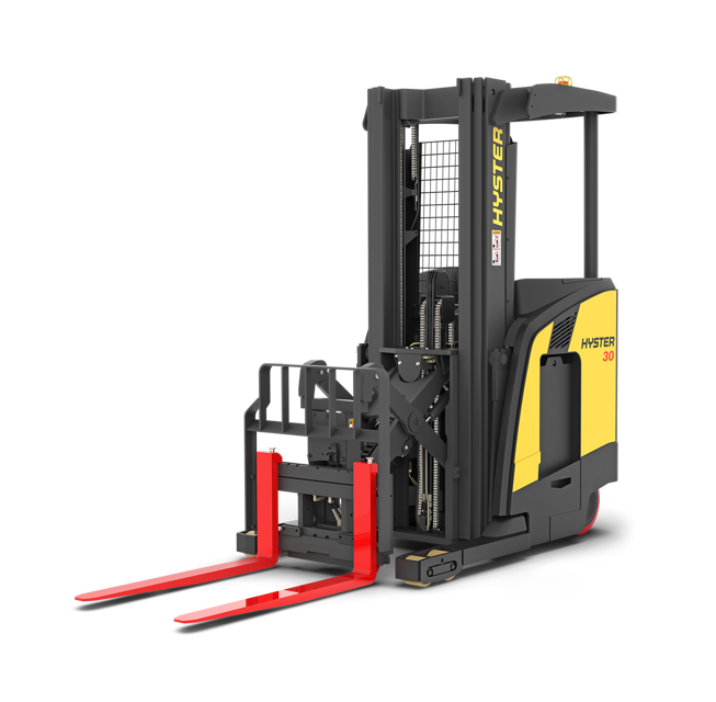
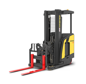
Hyster Forklift N40ZR2
Create an account to install this asset package.
Maintenance Plans for Hyster Forklift Model N40ZR2
Integrate maintenance plans directly into your work orders in MaintainX.
Drive Unit Assembling
WARNING: Cleaning solvents can be flammable and toxic and can cause skin irritation. When using cleaning solvents, always follow the recommendations of the manufacturer. Wear eye protection.
CAUTION: Some of the hardware used on the master drive unit (MDU) and traction motor is metric. Use the correct tool to avoid damage.
NOTE: The pinion gear and the large gear MUST be replaced as a set. The spiral bevel pinion and gear set MUST be replaced as a set.
NOTE: The large ball bearing is part of the top case. The top case and the ball bearing are replaced as a unit.
Clean all components thoroughly. Use Loctite® Fast Cleaner No. 706 to remove all traces of adhesive from the lower housing in the area where the thread-protecting shield had been located.
Check all parts for damage or cracks. Replace any damaged parts.
CAUTION: The axle and gear assemblies are installed and removed several times during this procedure. Be careful not to damage the seals.
NOTE: The helical pinion and gear and the bevel pinion shaft and bevel gear are matched sets and MUST be replaced as sets. When replacing the gear sets, always replace the tapered roller bearings.
Insert the special measuring tool in the pinion shaft lower bearing bore. Determine the correct thickness for the lower bearing shim set (dimension X) as follows (see Figure 7):

Initial 350 Hours Master Drive Unit Oil Change
Warning: The oil used in the master drive unit should be drained and replaced after 350 hours of initial operation in accordance with the maintenance schedule. After the initial oil change, the master drive unit requires only the addition of the recommended oil to maintain the oil at the proper level.
Is the oil warm?
If not, warm up the oil before proceeding.
Upload a photo of the drain and fill plugs.
Is a drain pan under the drain?
If not, place a drain pan under the drain to keep oil off the floor.
Is the drain plug installed?
If not, install the drain plug.
Enter the amount of oil added.
Master Drive Unit Removal
WARNING: The lift truck and components are heavy. All lifting devices (hoists, cables, chains, slings, etc.) must be suitable and of adequate capacity to lift the lift truck or component. The lift truck can weigh up to approximately 3541 kg (7800 lb) empty.
Move the steering control so the drive wheel is in a position for straight travel.
WARNING: Disconnect the battery and separate the connector before opening the drive unit compartment door and before inspecting or repairing the electrical system. If a tool causes a short circuit, the high-current flow from the battery can cause injury or parts damage.
Disconnect and remove the battery. Use the battery removal procedure described in either the Operating Manual or the section Periodic Maintenance 8000SRM1472.
Remove the electrical compartment cover for access to the traction motor controller.
WARNING: The capacitor in the traction motor controller can hold an electrical charge after the battery is disconnected. To prevent electrical shock or injury, discharge the capacitor before inspecting or repairing any component. Wear safety glasses. Make certain the battery has been disconnected.
Discharge the capacitor in the controller by connecting a 200-ohm, 2-watt resistor across the controller's a load across the B+ and B- terminals of the motor controller for 10 seconds. Remove the resistor after discharging the capacitor See Figure 18.
Open the drive unit compartment doors and fasten them so that they are fully open. Put a pan under the MDU drain plug and remove the plug. After the oil has completely drained, reinstall the drain plug. Tighten to 22 N•m (16 lbf ft).
WARNING: The motor is heavy. Use appropriate lifting equipment to avoid personal injury.
Drive Unit Removal
WARNING: The lift truck and components are heavy. Be sure that all lifting devices (hoists, cables, chains, slings, etc.) are suitable and of adequate capacity to lift the lift truck or component. The lift truck can weigh up to approximately 3541 kg (7800 lb) empty.
Move the steering control so the drive wheel is in a position for straight travel.
WARNING: Disconnect the battery and separate the connector before opening the drive unit compartment door and before inspecting or repairing the electrical system. If a tool causes a short circuit, the high-current flow from the battery can cause injury or parts damage.
Disconnect and remove the battery.
Remove the electrical compartment cover for access to the traction motor controller.
WARNING: The capacitor in the traction motor controller can hold an electrical charge after the battery is disconnected. To prevent electrical shock or injury, discharge the capacitor before inspecting or repairing any component. Wear safety glasses.
Discharge the traction motor controller by connecting a load across terminals B+ and B-.
Open the drive unit compartment door and drain the oil.
Remove the six capscrews and lockwashers that fasten the traction motor to the adapter ring on the MDU.
2000 Hourly Traction Motor And Drive Unit Splines Maintenance
CAUTION: The traction motor is only allowed to be lifted with soft ropes or belts, never with steel cables or chains. Care must be taken during transport to avoid shocks.
NOTE: The traction motor shaft and MDU input pinion splines should be lubricated every 2000 hours.
Traction motor removed from the drive unit?
Motor shaft splines and the drive unit input pinion wiped clean?
Upload a photo of the cleaned motor shaft splines and the drive unit input pinion
Dow Corning® Molykote G-N paste (or equivalent) (Hyster P/N 0339068) applied with a small brush to moderately coat internal MDU splines and external drive motor splines?
Upload a photo of the coated internal MDU splines and external drive motor splines
Motor reinstalled to the drive unit?
Sign off on the 2000 Hourly Traction Motor And Drive Unit Splines Maintenance
Parts for Hyster Forklift N40ZR2
Access the parts list for your equipment in MaintainX.
Special Measuring Tool
2036120
Special Clamping Tool
2036121
Dow Corning® Molykote G-N Paste
0339068
Special Measuring Tool
2036120
Special Clamping Tool
2036121
Dow Corning® Molykote G-N Paste
0339068
Special Measuring Tool
2036120
Special Clamping Tool
2036121
Dow Corning® Molykote G-N Paste
0339068
Unlock efficiency
with MaintainX CoPilot
MaintainX CoPilot is your expert colleague, on call 24/7, helping your team find the answers they need to keep equipment running.
Reduce Unplanned Downtime
Ensure your team follows consistent procedures to minimize equipment failures and costly delays.
Maximize Asset Availability
Keep your assets running longer and more reliably, with standardized maintenance workflows from OEM manuals.
Lower Maintenance Costs
Turn any technician into an expert to streamline operations, maintain more assets, and reduce overall costs.
Thousands of companies manage their assets with MaintainX

'%3e%3cpath%20fill='url(%23b)'%20d='M66.008%2080.068c-5.084-.786-9.763-3.834-12.442-8.68a16.942%2016.942%200%200%201-1.87-5.18c1.096.19%202.203.476%203.298.87%206.525%202.333%2010.836%207.68%2011.014%2012.99ZM51.47%2061.576c.488-5.524%203.62-10.716%208.847-13.597a17.132%2017.132%200%200%201%2011.335-1.882c-.798%208.145-7.43%2014.848-16.038%2015.599-1.417.119-2.799.07-4.144-.12Zm28.564-11.478a17.513%2017.513%200%200%201%203.727%204.62c4.608%208.335%201.584%2018.813-6.75%2023.409a16.988%2016.988%200%200%201-4.359%201.679%2019.624%2019.624%200%200%201-3.977-12.776c.346-7.561%204.942-13.931%2011.36-16.932Z'/%3e%3cpath%20fill='%23110F0D'%20fill-rule='evenodd'%20d='M142.831%2048.324h4.977V77.03h-4.977V48.324Zm27.278%2013.002c.322%201.048.453%202.263.453%203.62v12.073h-4.787V66.208c0-.75-.047-1.572-.154-2.143-.453-2.382-1.822-3.572-4.215-3.572-2.31%200-3.882%201.274-4.43%203.476-.143.596-.226%201.405-.226%202.25v10.8h-4.787V56.623h4.477v2.989c1.536-2.5%203.906-3.43%206.371-3.43%203.488%200%206.263%201.68%207.298%205.144Zm24.636%207.323c0%203.882-2.358%206.525-5.763%207.727-1.298.453-2.632.643-4.62.643h-10.169V48.324h9.085c1.691%200%203.156.143%204.049.38%203.465.93%205.727%203.68%205.727%207.335%200%202.441-.81%204.156-2.762%205.644%202.905%201.417%204.453%203.727%204.453%206.966Zm-15.634-8.656h4.584c1.024%200%201.917-.143%202.536-.417%201.215-.548%201.905-1.608%201.905-3.167%200-1.548-.643-2.572-1.845-3.132-.691-.31-1.762-.452-2.763-.452h-4.417v7.168Zm10.716%208.465c0-1.536-.893-3.37-3.227-3.893-.428-.095-1.036-.143-1.571-.143h-5.918v8.085h5.501c.56%200%201.429-.048%201.953-.167%201.94-.453%203.262-1.846%203.262-3.882Zm47.747-11.847-8.097%2020.408h-4.429l-8.109-20.408h5.191l5.192%2014.574%205.108-14.574h5.144Zm-20.218%2010.002c0%20.69-.036%201.262-.155%201.94h-15.943c.631%202.87%202.714%204.728%205.882%204.728%202.131%200%203.607-.882%204.703-2.525h4.87c-1.762%204.144-5.204%206.692-9.657%206.692-6.084%200-10.537-4.858-10.537-10.49%200-6.108%204.524-10.776%2010.335-10.776%206.239%200%2010.442%204.954%2010.502%2010.43Zm-4.763-1.405c-.333-2.846-2.643-4.858-5.691-4.858-2.894%200-5.287%201.929-5.621%204.858h11.312Zm-72.667%203.44c0%204.787-3.287%208.371-9.419%208.371H119.363V64.66c-1.917.274-3.87.69-5.811%201.238l4.537%2011.121h-5.418l-3.596-9.585c-5.144%202.084-10.085%205.216-14.217%209.585h-4.786L101.8%2048.312h4.56l5.68%2013.883a44.112%2044.112%200%200%201%207.323-1.774V48.312h9.084c1.703%200%203.156.143%204.061.393%203.453.929%205.727%203.667%205.727%207.323%200%201.917-.738%204.179-2.81%205.691%203.06%201.56%204.501%204.025%204.501%206.93Zm-15.634-8.667a62.664%2062.664%200%200%201%202.06-.036c1.703.012%203.239.131%204.608.37%201.441-.549%202.357-1.727%202.357-3.537%200-1.941-.881-3.144-2.488-3.667-.548-.18-1.358-.286-2.322-.286h-4.215v7.156Zm-16.55%203.905-3.715-9.894-6.394%2016.502c2.833-2.595%206.263-4.858%2010.109-6.608Zm27.254%204.74c0-2.775-3.131-4.347-8.513-4.418-.715%200-1.441.011-2.191.047v8.252h5.918c2.548%200%204.786-1.37%204.786-3.882Z'%20clip-rule='evenodd'/%3e%3c/g%3e%3cdefs%3e%3clinearGradient%20id='b'%20x1='51.47'%20x2='85.916'%20y1='62.946'%20y2='62.946'%20gradientUnits='userSpaceOnUse'%3e%3cstop%20stop-color='%23CD9F28'/%3e%3cstop%20offset='1'%20stop-color='%23ECD80B'/%3e%3c/linearGradient%3e%3cclipPath%20id='a'%3e%3cpath%20fill='%23fff'%20d='M51.47%2045.728h186.104V80.14H51.47z'/%3e%3c/clipPath%3e%3c/defs%3e%3c/svg%3e)


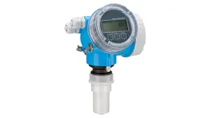
More from Hyster

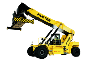


Explore Other Assets


© 2026 MaintainX. All rights reserved.