


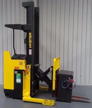
Hyster Forklift RS46-38L IH
Need answers fast?
Explore the manual using AI.

Turn manuals into instant answers
with your AI-powered assistantTurn manuals into instant answers
with your AI-powered assistant
Manual for Hyster Forklift RS46-38L IH
Complete asset maintenance, one click away
Get instant access to all the maintenance information you need. Empower technicians to perform preventive maintenance with asset packages, ready to use right out of the box.

Documents & Manuals
Find all the essential guides in one place.
 Tensioning Guide
- Belt-diagram
- C-120 pulleys
+ 13 more

Work Order Templates
Pre-built workflows to keep your asset running smoothly.
- Daily Electrical System Inspection
- Replace Roller and Pulley
- Install Engine B-120
+ 29 more

Procedures
Integrate maintenance plans directly into your work orders.
- Motion Industries
- Applied Industrial Technologies
- Electrical Brothers
+ 5 more

Parts
Access the parts list for your equipment in MaintainX.
- Drive Motor
- B2 Rollers
- Tensioning System
+ 40 more
Hyster Forklift RS46-38L IH
Create an account to install this asset package.
Maintenance Plans for Hyster Forklift Model RS46-38L IH
Integrate maintenance plans directly into your work orders in MaintainX.
Hydraulic Tank Breathers Maintenance
!NOTE: Never remove the safety stand pipe to avoid dirt from entering the hydraulic system.
Engine shut down and parking brake applied
Yellow button on the indicator pressed to release pressure
Cap loosened by turning counterclockwise
Filter cartridge removed
Inside of the housing cleaned with solvent
New filter cartridge inserted
Cap installed by turning clockwise
Engine started and operation of indicator checked

Derricking Circuit Disassemble
NOTE: Only use plugs that have been cleaned in solvent.
NOTE: In the event that seals are missing, check manifold for missing seals and remove.
NOTE: Cartridge valves are not field serviceable with exception of external seals and electrical solenoids. In event of a defective component, completely replace valve.
NOTE: Check load holding valve for cracks. If there are cracks in load holding valve, the load holding valve must be replaced.
The valve seals are serviceable parts of the load holding valve. Use the following procedures for repair:
Unscrew the cartridge valve from the load holding valve. See Figure 8.
Check that all seals are attached to cartridge valve.
Install a temporary plug in place of cartridge valve.
Sign off on the Derricking Circuit Disassemble
Cab Manifold Removal
WARNING: Lower boom completely before working on control valve or hydraulic system. The boom can lower suddenly and cause injury if the boom is not lowered.
Is the truck placed on a solid and level surface?
Is the boom lowered and the shutoff valves at the bottom of the hydraulic tank platform closed?
Is the engine shut down?
WARNING: Move all control levers back and forth a minimum of 20 times to remove all hydraulic pressure from pilot system.
Are the covers on the topside of the frame removed?
Are tags for identification put on hydraulic lines?
Are the hydraulic lines disconnected from the cab manifold?
Are caps put on the open lines, ports or other connectors?
Derricking Circuit Removal
!WARNING: Lower boom completely before working on control valve or hydraulic system. The boom can lower suddenly and cause injury if the boom is not lowered. This procedure will make sure that the boom cannot lower suddenly and cause injury or death.
!NOTE: All valves and other associated items installed on the load holding valve can be replaced. Before removal of any part, check that the area is clean and protected against dirt and fluid contamination.
Place the truck on a solid and level surface.
Lower boom and close the shutoff valves at the bottom of the hydraulic tank platform.
Shut down the engine.
!WARNING: Move all control levers back and forth a minimum of 20 times to remove all hydraulic pressure from pilot system.
Put tags for identification on electrical wires. Disconnect the electrical wires from the load holding valve.
Put tags for identification on hydraulic lines. Disconnect the hydraulic lines from the load holding valve. Put caps on the open lines, ports or other connectors.
Remove the four capscrews that fasten the load holding valve to the derricking cylinder.
Pump Output Check
Two methods are given for checking the volume of flow from the hydraulic pump. The first method uses a flow meter, a pressure gauge, and a needle valve. The second method uses a needle valve, a pressure gauge, a container, and a timer.
- First Method
1. If the flow meter is available, install flow meter between needle valve and outlet port of pump. See Figure 5. Pressure gauge must be between needle valve and pump. Make a separate check for each system.
When hydraulic oil is at operating temperature, run engine at 2100 rpm with no load on hydraulic system. Note reading of flow meter. Compare output rate of pump with specification found in the Specifications section.
!WARNING: Hydraulic oil can be hot. Do not touch oil during tests.
2. Run engine at high limit. Slowly close needle valve until gauge indicates a pressure just below specification for relief valve setting. Pump out- put at high pressure must be within 25% of out- put with no load. If output at high pressure is less than 75% of low pressure output, pump has a problem.
- Second Method
1. Another method of checking pump output is to measure the amount of oil moved in a given amount of time. See Figure 6. Run engine until oil is 55 to 65 C (130 to 150 F).
Disconnect line from outlet port of pump. Install a 0 to 21 MPa (0 to 3050 psi) pressure gauge on a tee fitting connected to a hose from outlet port. Install needle valve on end of hose.
Unlock efficiency
with MaintainX CoPilot
MaintainX CoPilot is your expert colleague, on call 24/7, helping your team find the answers they need to keep equipment running.
Reduce Unplanned Downtime
Ensure your team follows consistent procedures to minimize equipment failures and costly delays.
Maximize Asset Availability
Keep your assets running longer and more reliably, with standardized maintenance workflows from OEM manuals.
Lower Maintenance Costs
Turn any technician into an expert to streamline operations, maintain more assets, and reduce overall costs.
Thousands of companies manage their assets with MaintainX

'%3e%3cpath%20fill='url(%23b)'%20d='M66.008%2080.068c-5.084-.786-9.763-3.834-12.442-8.68a16.942%2016.942%200%200%201-1.87-5.18c1.096.19%202.203.476%203.298.87%206.525%202.333%2010.836%207.68%2011.014%2012.99ZM51.47%2061.576c.488-5.524%203.62-10.716%208.847-13.597a17.132%2017.132%200%200%201%2011.335-1.882c-.798%208.145-7.43%2014.848-16.038%2015.599-1.417.119-2.799.07-4.144-.12Zm28.564-11.478a17.513%2017.513%200%200%201%203.727%204.62c4.608%208.335%201.584%2018.813-6.75%2023.409a16.988%2016.988%200%200%201-4.359%201.679%2019.624%2019.624%200%200%201-3.977-12.776c.346-7.561%204.942-13.931%2011.36-16.932Z'/%3e%3cpath%20fill='%23110F0D'%20fill-rule='evenodd'%20d='M142.831%2048.324h4.977V77.03h-4.977V48.324Zm27.278%2013.002c.322%201.048.453%202.263.453%203.62v12.073h-4.787V66.208c0-.75-.047-1.572-.154-2.143-.453-2.382-1.822-3.572-4.215-3.572-2.31%200-3.882%201.274-4.43%203.476-.143.596-.226%201.405-.226%202.25v10.8h-4.787V56.623h4.477v2.989c1.536-2.5%203.906-3.43%206.371-3.43%203.488%200%206.263%201.68%207.298%205.144Zm24.636%207.323c0%203.882-2.358%206.525-5.763%207.727-1.298.453-2.632.643-4.62.643h-10.169V48.324h9.085c1.691%200%203.156.143%204.049.38%203.465.93%205.727%203.68%205.727%207.335%200%202.441-.81%204.156-2.762%205.644%202.905%201.417%204.453%203.727%204.453%206.966Zm-15.634-8.656h4.584c1.024%200%201.917-.143%202.536-.417%201.215-.548%201.905-1.608%201.905-3.167%200-1.548-.643-2.572-1.845-3.132-.691-.31-1.762-.452-2.763-.452h-4.417v7.168Zm10.716%208.465c0-1.536-.893-3.37-3.227-3.893-.428-.095-1.036-.143-1.571-.143h-5.918v8.085h5.501c.56%200%201.429-.048%201.953-.167%201.94-.453%203.262-1.846%203.262-3.882Zm47.747-11.847-8.097%2020.408h-4.429l-8.109-20.408h5.191l5.192%2014.574%205.108-14.574h5.144Zm-20.218%2010.002c0%20.69-.036%201.262-.155%201.94h-15.943c.631%202.87%202.714%204.728%205.882%204.728%202.131%200%203.607-.882%204.703-2.525h4.87c-1.762%204.144-5.204%206.692-9.657%206.692-6.084%200-10.537-4.858-10.537-10.49%200-6.108%204.524-10.776%2010.335-10.776%206.239%200%2010.442%204.954%2010.502%2010.43Zm-4.763-1.405c-.333-2.846-2.643-4.858-5.691-4.858-2.894%200-5.287%201.929-5.621%204.858h11.312Zm-72.667%203.44c0%204.787-3.287%208.371-9.419%208.371H119.363V64.66c-1.917.274-3.87.69-5.811%201.238l4.537%2011.121h-5.418l-3.596-9.585c-5.144%202.084-10.085%205.216-14.217%209.585h-4.786L101.8%2048.312h4.56l5.68%2013.883a44.112%2044.112%200%200%201%207.323-1.774V48.312h9.084c1.703%200%203.156.143%204.061.393%203.453.929%205.727%203.667%205.727%207.323%200%201.917-.738%204.179-2.81%205.691%203.06%201.56%204.501%204.025%204.501%206.93Zm-15.634-8.667a62.664%2062.664%200%200%201%202.06-.036c1.703.012%203.239.131%204.608.37%201.441-.549%202.357-1.727%202.357-3.537%200-1.941-.881-3.144-2.488-3.667-.548-.18-1.358-.286-2.322-.286h-4.215v7.156Zm-16.55%203.905-3.715-9.894-6.394%2016.502c2.833-2.595%206.263-4.858%2010.109-6.608Zm27.254%204.74c0-2.775-3.131-4.347-8.513-4.418-.715%200-1.441.011-2.191.047v8.252h5.918c2.548%200%204.786-1.37%204.786-3.882Z'%20clip-rule='evenodd'/%3e%3c/g%3e%3cdefs%3e%3clinearGradient%20id='b'%20x1='51.47'%20x2='85.916'%20y1='62.946'%20y2='62.946'%20gradientUnits='userSpaceOnUse'%3e%3cstop%20stop-color='%23CD9F28'/%3e%3cstop%20offset='1'%20stop-color='%23ECD80B'/%3e%3c/linearGradient%3e%3cclipPath%20id='a'%3e%3cpath%20fill='%23fff'%20d='M51.47%2045.728h186.104V80.14H51.47z'/%3e%3c/clipPath%3e%3c/defs%3e%3c/svg%3e)


More from Hyster


Explore Other Assets


© 2026 MaintainX. All rights reserved.