


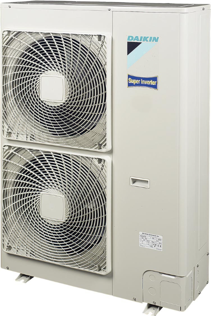
Daikin Outdoor Unit Air Conditioner RZQ100D7V1
Need answers fast?
Explore the manual using AI.
Turn manuals into instant answers
with your AI-powered assistantTurn manuals into instant answers
with your AI-powered assistant
Manual for Daikin Outdoor Unit Air Conditioner RZQ100D7V1
Complete asset maintenance, one click away
Get instant access to all the maintenance information you need. Empower technicians to perform preventive maintenance with asset packages, ready to use right out of the box.

Documents & Manuals
Find all the essential guides in one place.
 Tensioning Guide
- Belt-diagram
- C-120 pulleys
+ 13 more

Work Order Templates
Pre-built workflows to keep your asset running smoothly.
- Daily Electrical System Inspection
- Replace Roller and Pulley
- Install Engine B-120
+ 29 more

Procedures
Integrate maintenance plans directly into your work orders.
- Motion Industries
- Applied Industrial Technologies
- Electrical Brothers
+ 5 more

Parts
Access the parts list for your equipment in MaintainX.
- Drive Motor
- B2 Rollers
- Tensioning System
+ 40 more
Daikin Outdoor Unit Air Conditioner RZQ100D7V1
Create an account to install this asset package.
Maintenance Plans for Daikin Outdoor Unit Air Conditioner Model RZQ100D7V1
Integrate maintenance plans directly into your work orders in MaintainX.
Pressure Sensor / Electronic Expansion Valve Removal
Warning: Be sure to commence the disassembling work after 10 minutes or more elapsed from all power supplies have been turned off.
Remove the top panel and the front panel (2) accordance with the Removal Procedure for Outside Panels.
Before removing the solenoid valve or the electronic expantion valve, be sure to recover the refrigerant.
Precaution for mounting the coil for the electronic expantion valve
Align the dimple of the electronic expantion valve and the stopper of the coil for the electronic expantion valve, and then push them in until you hear them click.
1. Remove the pressure sensor
1 Disconnect the pressure sensor connector (X17A).
2 Use two spanners to remove the pressure sensor.
2. Remove the solenoid valve

PC Board Removal
Warning: Be sure to commence the disassembling work after 10 minutes or more elapsed from all power supplies have been turned off.
Remove the top panel and the front panel (2) accordance with the Removal Procedure for Outside Panels.
1. Remove the PC board (A2P)
1 Disconnect the connector (X205A) from the PC board.
2 While pressing the two hooks, remove the PC board (A2P).
2. Remove the PC board (A1P)
Remove the switch box accordance with the Removal procedure for the switch box.
1 Remove the clamp from the compressor harness.
2 Press the hooks to remove the terminal block.
Compressor Removal
Warning: Be sure to commence the disassembling work after 10 minutes or more elapsed from all power supplies have been turned off.
Recover the refrigerant
Remove the front panel (2) and the front piping cover bracket
Be sure to remove the compressor only after the refrigerant is completely recovered.
Remove Terminal block
One out of the nuts that fix the compressor is located outside of the partition panel.
Be sure to cut thee pipes by using a pipe cutter before disconnecting the brazed sections of pipes. A sudden disconnection of the brazed sections can cause oil to catch fire.
Unscrew the five screws that fix the stop valve mounting plate, and then remove this mounting plate.
Remove the gas piping and the liquid piping.
Four Way Valve Removal
Warning: Be sure to commence the disassembling work after 10 minutes or more elapsed from all power supplies have been turned off.
Refrigerant recovered
According to the procedure for the removal related to the outside panel, remove the front panel (2) and the side panel.
According to the procedure for the removal of switch box, remove the switch box.
Four way valve removed only after the refrigerant is completely recovered.
1 Unscrew the one screw that fixes the coil for the four way valve, and then remove this coil.
2 Remove brazing from the four places, and then remove the four way valve. (Refer to point column.)
To prevent the four way valve from exceeding a temperature of 120°C, conduct brazing work while cooling the valve with wet cloths or else.
Sign off on the valve removal
Thermistor Removal
Warning: Be sure to commence the disassembling work after 10 minutes or more elapsed from all power supplies have been turned off.
Remove the top panel and the front panel (2) and side panel accordance with the Procedure for Outside Panels.
Pull out the outdoor air temperature thermistor to the front, and then slide this thermistor to the right to remove it.
Pinch the mounting spring that fixes the discharge pipe thermistor to pull out this thermistor.
Press the fixing section of the suction pipe thermistor to pull out this thermistor.
Pull the fixing bracket of the heat exchanger’s distribution pipe thermistor to the front, and then remove this thermistor.
Press the fixing section of the heat exchanger’s intermediate temperature thermistor to pull out this thermistor.
*1 The heat exchanger’s distribution pipe thermistor, heat exchanger’s intermediate temperature thermistor, and liquid pipe thermistor are jointed together with a single connector. Consequently, these three thermistors should be replaced at the same time.
Press the fixing section of the liquid pipe thermistor to pull out this thermistor.
Unlock efficiency
with MaintainX CoPilot
MaintainX CoPilot is your expert colleague, on call 24/7, helping your team find the answers they need to keep equipment running.
Reduce Unplanned Downtime
Ensure your team follows consistent procedures to minimize equipment failures and costly delays.
Maximize Asset Availability
Keep your assets running longer and more reliably, with standardized maintenance workflows from OEM manuals.
Lower Maintenance Costs
Turn any technician into an expert to streamline operations, maintain more assets, and reduce overall costs.
Thousands of companies manage their assets with MaintainX

'%3e%3cpath%20fill='url(%23b)'%20d='M66.008%2080.068c-5.084-.786-9.763-3.834-12.442-8.68a16.942%2016.942%200%200%201-1.87-5.18c1.096.19%202.203.476%203.298.87%206.525%202.333%2010.836%207.68%2011.014%2012.99ZM51.47%2061.576c.488-5.524%203.62-10.716%208.847-13.597a17.132%2017.132%200%200%201%2011.335-1.882c-.798%208.145-7.43%2014.848-16.038%2015.599-1.417.119-2.799.07-4.144-.12Zm28.564-11.478a17.513%2017.513%200%200%201%203.727%204.62c4.608%208.335%201.584%2018.813-6.75%2023.409a16.988%2016.988%200%200%201-4.359%201.679%2019.624%2019.624%200%200%201-3.977-12.776c.346-7.561%204.942-13.931%2011.36-16.932Z'/%3e%3cpath%20fill='%23110F0D'%20fill-rule='evenodd'%20d='M142.831%2048.324h4.977V77.03h-4.977V48.324Zm27.278%2013.002c.322%201.048.453%202.263.453%203.62v12.073h-4.787V66.208c0-.75-.047-1.572-.154-2.143-.453-2.382-1.822-3.572-4.215-3.572-2.31%200-3.882%201.274-4.43%203.476-.143.596-.226%201.405-.226%202.25v10.8h-4.787V56.623h4.477v2.989c1.536-2.5%203.906-3.43%206.371-3.43%203.488%200%206.263%201.68%207.298%205.144Zm24.636%207.323c0%203.882-2.358%206.525-5.763%207.727-1.298.453-2.632.643-4.62.643h-10.169V48.324h9.085c1.691%200%203.156.143%204.049.38%203.465.93%205.727%203.68%205.727%207.335%200%202.441-.81%204.156-2.762%205.644%202.905%201.417%204.453%203.727%204.453%206.966Zm-15.634-8.656h4.584c1.024%200%201.917-.143%202.536-.417%201.215-.548%201.905-1.608%201.905-3.167%200-1.548-.643-2.572-1.845-3.132-.691-.31-1.762-.452-2.763-.452h-4.417v7.168Zm10.716%208.465c0-1.536-.893-3.37-3.227-3.893-.428-.095-1.036-.143-1.571-.143h-5.918v8.085h5.501c.56%200%201.429-.048%201.953-.167%201.94-.453%203.262-1.846%203.262-3.882Zm47.747-11.847-8.097%2020.408h-4.429l-8.109-20.408h5.191l5.192%2014.574%205.108-14.574h5.144Zm-20.218%2010.002c0%20.69-.036%201.262-.155%201.94h-15.943c.631%202.87%202.714%204.728%205.882%204.728%202.131%200%203.607-.882%204.703-2.525h4.87c-1.762%204.144-5.204%206.692-9.657%206.692-6.084%200-10.537-4.858-10.537-10.49%200-6.108%204.524-10.776%2010.335-10.776%206.239%200%2010.442%204.954%2010.502%2010.43Zm-4.763-1.405c-.333-2.846-2.643-4.858-5.691-4.858-2.894%200-5.287%201.929-5.621%204.858h11.312Zm-72.667%203.44c0%204.787-3.287%208.371-9.419%208.371H119.363V64.66c-1.917.274-3.87.69-5.811%201.238l4.537%2011.121h-5.418l-3.596-9.585c-5.144%202.084-10.085%205.216-14.217%209.585h-4.786L101.8%2048.312h4.56l5.68%2013.883a44.112%2044.112%200%200%201%207.323-1.774V48.312h9.084c1.703%200%203.156.143%204.061.393%203.453.929%205.727%203.667%205.727%207.323%200%201.917-.738%204.179-2.81%205.691%203.06%201.56%204.501%204.025%204.501%206.93Zm-15.634-8.667a62.664%2062.664%200%200%201%202.06-.036c1.703.012%203.239.131%204.608.37%201.441-.549%202.357-1.727%202.357-3.537%200-1.941-.881-3.144-2.488-3.667-.548-.18-1.358-.286-2.322-.286h-4.215v7.156Zm-16.55%203.905-3.715-9.894-6.394%2016.502c2.833-2.595%206.263-4.858%2010.109-6.608Zm27.254%204.74c0-2.775-3.131-4.347-8.513-4.418-.715%200-1.441.011-2.191.047v8.252h5.918c2.548%200%204.786-1.37%204.786-3.882Z'%20clip-rule='evenodd'/%3e%3c/g%3e%3cdefs%3e%3clinearGradient%20id='b'%20x1='51.47'%20x2='85.916'%20y1='62.946'%20y2='62.946'%20gradientUnits='userSpaceOnUse'%3e%3cstop%20stop-color='%23CD9F28'/%3e%3cstop%20offset='1'%20stop-color='%23ECD80B'/%3e%3c/linearGradient%3e%3cclipPath%20id='a'%3e%3cpath%20fill='%23fff'%20d='M51.47%2045.728h186.104V80.14H51.47z'/%3e%3c/clipPath%3e%3c/defs%3e%3c/svg%3e)


More from Daikin


Explore Other Assets


© 2026 MaintainX. All rights reserved.