


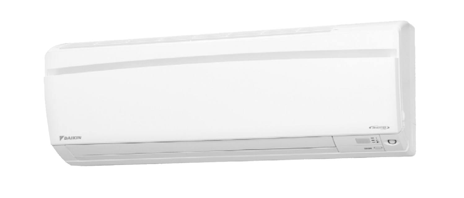
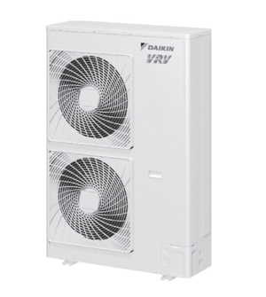
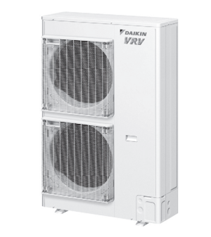
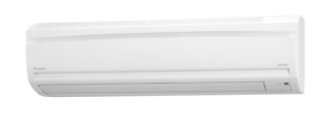
Daikin Indoor Unit Cooling Only Air Conditioner FTKV25NVM
Need answers fast?
Explore the manual using AI.
Turn manuals into instant answers
with your AI-powered assistantTurn manuals into instant answers
with your AI-powered assistant
Complete asset maintenance, one click away
Get instant access to all the maintenance information you need. Empower technicians to perform preventive maintenance with asset packages, ready to use right out of the box.

Documents & Manuals
Find all the essential guides in one place.
 Tensioning Guide
- Belt-diagram
- C-120 pulleys
+ 13 more

Work Order Templates
Pre-built workflows to keep your asset running smoothly.
- Daily Electrical System Inspection
- Replace Roller and Pulley
- Install Engine B-120
+ 29 more

Procedures
Integrate maintenance plans directly into your work orders.
- Motion Industries
- Applied Industrial Technologies
- Electrical Brothers
+ 5 more

Parts
Access the parts list for your equipment in MaintainX.
- Drive Motor
- B2 Rollers
- Tensioning System
+ 40 more
Daikin Indoor Unit Cooling Only Air Conditioner FTKV25NVM
Create an account to install this asset package.
Maintenance Plans for Daikin Indoor Unit Cooling Only Air Conditioner Model FTKV25NVM
Integrate maintenance plans directly into your work orders in MaintainX.
Horizontal Blade / Vertical Blade ASSY Removal
Warning: Be sure to wait for 10 minutes or more after turning off all power supplies before disassembling work.
1. Remove the horizontal blades.
When reassembling, mount the large horizontal blade to the upper position and the small horizontal blade to the lower position.
Do not install them in the wrong place.
1) Unfasten the center shaft while bending the horizontal blade (upper) slightly.
2) Unfasten the left shaft.
3) Unfasten the right shaft.
4) Remove the horizontal blade (lower) in the same way.
Installation procedure

Indoor Heat Exchanger Removal
Warning: Be sure to wait for 10 minutes or more after turning off all power supplies before disassembling work.
In pump-down work, be sure to stop the compressor before disconnecting the refrigerant pipe. If the refrigerant pipe is disconnected with the compressor operating and the stop valve open, air may be sucked in and may generate an over-pressure in refrigeration cycle, thus resulting in pipe rupture or accidental injury.
When removing or reinstalling the indoor heat exchanger, be sure to wear gloves or wrap the indoor heat exchanger with cloths. (You may be injured by the fins.)
Caution: Be sure to conduct pump down operation before disassembling the refrigerant pipe. If the refrigerant leaks, repair the spot of leaking, then collect all refrigerant from the unit. After conducting vacuum drying, recharge proper amount of refrigerant. From the viewpoint of global environmental protection, make sure to use a vacuum pump for air purging.
Remove the 2 screws which fix the indoor heat exchanger to the installation plate.
Disconnect the pipings. Place a plastic sheet under the drain pan to prevent from wetting the floor with remaining drain. If the drain hose is embedded in the wall, disconnect the drain hose beforehand. Carry out the removal work with 2 wrenches. When the pipings are disconnected, protect both the openings of pipe and unit from entering of moisture. Inserting a wooden base beneath the unit facilitates the removing work.
Remove the indoor unit from the installation plate.
Unfasten the hook of the piping fixture at the back of the indoor unit and pull out the piping.
Slightly widen the auxiliary piping.
Fan Rotor Removal
Warning: Be sure to wait for 10 minutes or more after turning off all power supplies before disassembling work.
Remove the 2 screws of the right side plate.
Release the fan motor lead wire from the hooks and remove the right side plate.
When reassembling the fan motor and the fan rotor, provide as much as 5 mm (0.2 inch) of play between the side face of the rotor and the bottom frame.
Insert the fan motor with approx. 5 mm (0.2 inch) left.
Tighten the screw until it stops. Then give the screw one more turn.
Rotate the fan rotor and confirm the fan motor and the fan rotor are installed appropriately.
Tighten the screw completely if appropriate.
If not appropriate, go back to (1).
Air Filter Removal
Warning: Be sure to wait for 10 minutes or more after turning off all power supplies before disassembling work.
1. Remove the air filters.
The air filter is not marked for difference between the right and left sides.
Insert the air filter with the “FRONT” mark faced up.
The air filter can be set easily by inserting it along the guides.
Be sure to insert the hooks (at 2 lower positions) when mounting the air filter.
1) Open the front panel.
2) Pull out the air filter downward and remove it.
2. Remove the Titanium apatite photocatalytic airpurifying filters.
PCB Removal
Warning: Be sure to wait for 10 minutes or more after turning off all power supplies before disassembling work.
1. Remove the shield plate.
1) The figure shows the appearance of the electrical box.
2) Open the shield plate.
3) Push the upper center of the shield plate and unfasten the 2 hooks.
Remove the shield plate.
2. Release the indoor heat exchanger thermistor.
1) Release the indoor heat exchanger thermistor and the earth / ground wire from the hooks.
3. Remove the terminal board.
Unlock efficiency
with MaintainX CoPilot
MaintainX CoPilot is your expert colleague, on call 24/7, helping your team find the answers they need to keep equipment running.
Reduce Unplanned Downtime
Ensure your team follows consistent procedures to minimize equipment failures and costly delays.
Maximize Asset Availability
Keep your assets running longer and more reliably, with standardized maintenance workflows from OEM manuals.
Lower Maintenance Costs
Turn any technician into an expert to streamline operations, maintain more assets, and reduce overall costs.
Thousands of companies manage their assets with MaintainX

'%3e%3cpath%20fill='url(%23b)'%20d='M66.008%2080.068c-5.084-.786-9.763-3.834-12.442-8.68a16.942%2016.942%200%200%201-1.87-5.18c1.096.19%202.203.476%203.298.87%206.525%202.333%2010.836%207.68%2011.014%2012.99ZM51.47%2061.576c.488-5.524%203.62-10.716%208.847-13.597a17.132%2017.132%200%200%201%2011.335-1.882c-.798%208.145-7.43%2014.848-16.038%2015.599-1.417.119-2.799.07-4.144-.12Zm28.564-11.478a17.513%2017.513%200%200%201%203.727%204.62c4.608%208.335%201.584%2018.813-6.75%2023.409a16.988%2016.988%200%200%201-4.359%201.679%2019.624%2019.624%200%200%201-3.977-12.776c.346-7.561%204.942-13.931%2011.36-16.932Z'/%3e%3cpath%20fill='%23110F0D'%20fill-rule='evenodd'%20d='M142.831%2048.324h4.977V77.03h-4.977V48.324Zm27.278%2013.002c.322%201.048.453%202.263.453%203.62v12.073h-4.787V66.208c0-.75-.047-1.572-.154-2.143-.453-2.382-1.822-3.572-4.215-3.572-2.31%200-3.882%201.274-4.43%203.476-.143.596-.226%201.405-.226%202.25v10.8h-4.787V56.623h4.477v2.989c1.536-2.5%203.906-3.43%206.371-3.43%203.488%200%206.263%201.68%207.298%205.144Zm24.636%207.323c0%203.882-2.358%206.525-5.763%207.727-1.298.453-2.632.643-4.62.643h-10.169V48.324h9.085c1.691%200%203.156.143%204.049.38%203.465.93%205.727%203.68%205.727%207.335%200%202.441-.81%204.156-2.762%205.644%202.905%201.417%204.453%203.727%204.453%206.966Zm-15.634-8.656h4.584c1.024%200%201.917-.143%202.536-.417%201.215-.548%201.905-1.608%201.905-3.167%200-1.548-.643-2.572-1.845-3.132-.691-.31-1.762-.452-2.763-.452h-4.417v7.168Zm10.716%208.465c0-1.536-.893-3.37-3.227-3.893-.428-.095-1.036-.143-1.571-.143h-5.918v8.085h5.501c.56%200%201.429-.048%201.953-.167%201.94-.453%203.262-1.846%203.262-3.882Zm47.747-11.847-8.097%2020.408h-4.429l-8.109-20.408h5.191l5.192%2014.574%205.108-14.574h5.144Zm-20.218%2010.002c0%20.69-.036%201.262-.155%201.94h-15.943c.631%202.87%202.714%204.728%205.882%204.728%202.131%200%203.607-.882%204.703-2.525h4.87c-1.762%204.144-5.204%206.692-9.657%206.692-6.084%200-10.537-4.858-10.537-10.49%200-6.108%204.524-10.776%2010.335-10.776%206.239%200%2010.442%204.954%2010.502%2010.43Zm-4.763-1.405c-.333-2.846-2.643-4.858-5.691-4.858-2.894%200-5.287%201.929-5.621%204.858h11.312Zm-72.667%203.44c0%204.787-3.287%208.371-9.419%208.371H119.363V64.66c-1.917.274-3.87.69-5.811%201.238l4.537%2011.121h-5.418l-3.596-9.585c-5.144%202.084-10.085%205.216-14.217%209.585h-4.786L101.8%2048.312h4.56l5.68%2013.883a44.112%2044.112%200%200%201%207.323-1.774V48.312h9.084c1.703%200%203.156.143%204.061.393%203.453.929%205.727%203.667%205.727%207.323%200%201.917-.738%204.179-2.81%205.691%203.06%201.56%204.501%204.025%204.501%206.93Zm-15.634-8.667a62.664%2062.664%200%200%201%202.06-.036c1.703.012%203.239.131%204.608.37%201.441-.549%202.357-1.727%202.357-3.537%200-1.941-.881-3.144-2.488-3.667-.548-.18-1.358-.286-2.322-.286h-4.215v7.156Zm-16.55%203.905-3.715-9.894-6.394%2016.502c2.833-2.595%206.263-4.858%2010.109-6.608Zm27.254%204.74c0-2.775-3.131-4.347-8.513-4.418-.715%200-1.441.011-2.191.047v8.252h5.918c2.548%200%204.786-1.37%204.786-3.882Z'%20clip-rule='evenodd'/%3e%3c/g%3e%3cdefs%3e%3clinearGradient%20id='b'%20x1='51.47'%20x2='85.916'%20y1='62.946'%20y2='62.946'%20gradientUnits='userSpaceOnUse'%3e%3cstop%20stop-color='%23CD9F28'/%3e%3cstop%20offset='1'%20stop-color='%23ECD80B'/%3e%3c/linearGradient%3e%3cclipPath%20id='a'%3e%3cpath%20fill='%23fff'%20d='M51.47%2045.728h186.104V80.14H51.47z'/%3e%3c/clipPath%3e%3c/defs%3e%3c/svg%3e)


More from Daikin


Explore Other Assets


© 2026 MaintainX. All rights reserved.