


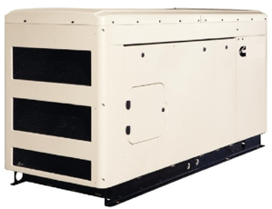
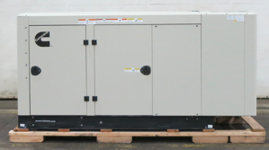
Cummins Diesel Generators C500D6
Need answers fast?
Explore the manual using AI.
The Cummins Diesel Generator C500D6 is a robust and reliable power solution designed for industrial applications. Known for its durability and efficiency, this generator model provides dependable performance and is ideal for various operational needs, ensuring continuous power supply in demanding environments.
Turn manuals into instant answers
with your AI-powered assistantTurn manuals into instant answers
with your AI-powered assistant
Manual for Cummins Diesel Generators C500D6
Complete asset maintenance, one click away
Get instant access to all the maintenance information you need. Empower technicians to perform preventive maintenance with asset packages, ready to use right out of the box.

Documents & Manuals
Find all the essential guides in one place.
 Tensioning Guide
- Belt-diagram
- C-120 pulleys
+ 13 more

Work Order Templates
Pre-built workflows to keep your asset running smoothly.
- Daily Electrical System Inspection
- Replace Roller and Pulley
- Install Engine B-120
+ 29 more

Procedures
Integrate maintenance plans directly into your work orders.
- Motion Industries
- Applied Industrial Technologies
- Electrical Brothers
+ 5 more

Parts
Access the parts list for your equipment in MaintainX.
- Drive Motor
- B2 Rollers
- Tensioning System
+ 40 more
Cummins Diesel Generators C500D6
Create an account to install this asset package.
Maintenance Plans for Cummins Diesel Generators Model C500D6
Integrate maintenance plans directly into your work orders in MaintainX.
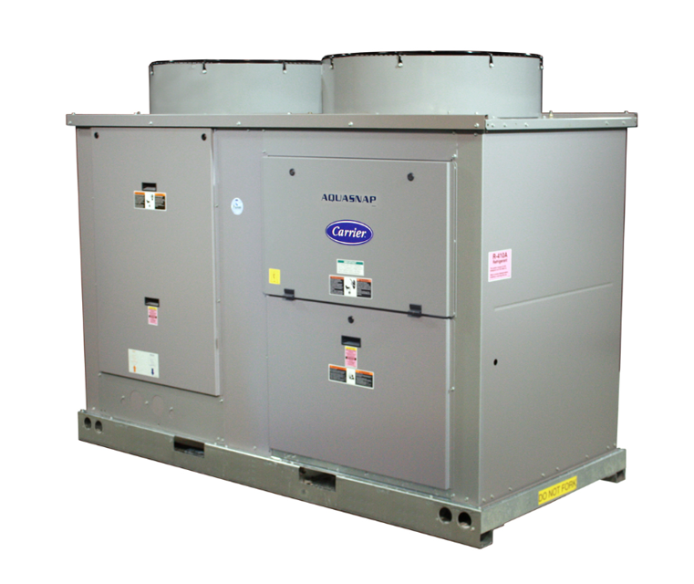
VICTAULIC COUPLING INSTALLATION
Warning: Ensure the outside surface of the pipe is smooth and free from indentations, projections, and roll marks
Is the pipe surface clean from oil, grease, loose paint, and dirt?
Apply a thin coat of Victaulic lubricant or silicone lubricant to the gasket sealing lips and exterior
Is the gasket positioned correctly over the pipe end?
Are the two pipe ends aligned and brought together?
Is the gasket centered between the groove in each pipe end?
Are the housings installed over the gasket correctly?
Ensure the housings’ keys engage the grooves completely on both pipe ends
Are the bolts installed and a nut finger-tight onto each bolt?

The System Maintenance
FILLING THE SYSTEM
The entire piping system filled with water
Pressure at the top of the system (should be at least 4 psig [28 kPa])
Pressure at all points in the system high enough to prevent flashing in the piping or cavitation in the pump
The best location to install the fill connection is close to the expansion tank. An air vent should be installed close by to help eliminate air that enters during the fill procedure.
Temporary bypass piping and cleaning/flushing equipment removed
All drain plugs are installed
Blow-down valve opened to flush the strainer
Normally, a closed system needs to be filled only once. The actual filling process is generally a fairly simple procedure. All air should be purged or vented from the system. Thorough venting at the high points and circulation at room temperature for several hours is recommended.
Mounting Unit Maintenance
Ensure the unit is in the proper location and secured to the supporting structure.
Is the unit level to within 1/8 in. (.32 mm) per foot for proper oil return to compressor?
Check Compressor Mounting
Are units with single compressors held down with 4 bolts through rubber grommets?
Are units with tandem compressors held down with 6 bolts per pair through grommets?
Verify mounting bolt torque 7 to 10 ft-lb (9.5 to 13.6 N•m)
For 30RAP100-150 units, remove RED bolts from compressor mounting rail and RED shipping braces.
Connect Cooler Fluid and Drain Piping
Is the strainer in place?
The compression tank Maintenance
Warning: This maintenance check requires trained personnel with PPE!
Does the compression tank provide net positive suction head required (NPSHR) for the pump to operate satisfactorily?
Enter the system pressure
Does the compression tank accommodate expansion/contraction of water due to temperature changes?
Does the compression tank act as a pressure reference for the pump?
Sign off on the compression tank maintenance
Air Separation Maintenance
Warning: This procedure requires trained personnel with PPE!
Free air in the system causing noise or reducing terminal output?
If free air is causing issues, report to the maintenance team and stop the procedure
Choose the location of air separator installation
Enter the water temperature at the point of air separator installation
Enter the water pressure at the point of air separator installation
Air separator installed at the point of highest water temperature and lowest pressure?
If not, specify the reason
Enter the water velocity
Parts for Cummins Diesel Generators C500D6
Access the parts list for your equipment in MaintainX.
Dual Leaving Water Thermistor Wel
10HB50106801
Dual Leaving Water Thermistor Wel
10HB50106802
Dual Leaving Water Thermistor Wel
10HB50106801
Dual Leaving Water Thermistor Wel
10HB50106802
Dual Leaving Water Thermistor Wel
10HB50106801
Dual Leaving Water Thermistor Wel
10HB50106802
Unlock efficiency
with MaintainX CoPilot
MaintainX CoPilot is your expert colleague, on call 24/7, helping your team find the answers they need to keep equipment running.
Reduce Unplanned Downtime
Ensure your team follows consistent procedures to minimize equipment failures and costly delays.
Maximize Asset Availability
Keep your assets running longer and more reliably, with standardized maintenance workflows from OEM manuals.
Lower Maintenance Costs
Turn any technician into an expert to streamline operations, maintain more assets, and reduce overall costs.
Thousands of companies manage their assets with MaintainX

'%3e%3cpath%20fill='url(%23b)'%20d='M66.008%2080.068c-5.084-.786-9.763-3.834-12.442-8.68a16.942%2016.942%200%200%201-1.87-5.18c1.096.19%202.203.476%203.298.87%206.525%202.333%2010.836%207.68%2011.014%2012.99ZM51.47%2061.576c.488-5.524%203.62-10.716%208.847-13.597a17.132%2017.132%200%200%201%2011.335-1.882c-.798%208.145-7.43%2014.848-16.038%2015.599-1.417.119-2.799.07-4.144-.12Zm28.564-11.478a17.513%2017.513%200%200%201%203.727%204.62c4.608%208.335%201.584%2018.813-6.75%2023.409a16.988%2016.988%200%200%201-4.359%201.679%2019.624%2019.624%200%200%201-3.977-12.776c.346-7.561%204.942-13.931%2011.36-16.932Z'/%3e%3cpath%20fill='%23110F0D'%20fill-rule='evenodd'%20d='M142.831%2048.324h4.977V77.03h-4.977V48.324Zm27.278%2013.002c.322%201.048.453%202.263.453%203.62v12.073h-4.787V66.208c0-.75-.047-1.572-.154-2.143-.453-2.382-1.822-3.572-4.215-3.572-2.31%200-3.882%201.274-4.43%203.476-.143.596-.226%201.405-.226%202.25v10.8h-4.787V56.623h4.477v2.989c1.536-2.5%203.906-3.43%206.371-3.43%203.488%200%206.263%201.68%207.298%205.144Zm24.636%207.323c0%203.882-2.358%206.525-5.763%207.727-1.298.453-2.632.643-4.62.643h-10.169V48.324h9.085c1.691%200%203.156.143%204.049.38%203.465.93%205.727%203.68%205.727%207.335%200%202.441-.81%204.156-2.762%205.644%202.905%201.417%204.453%203.727%204.453%206.966Zm-15.634-8.656h4.584c1.024%200%201.917-.143%202.536-.417%201.215-.548%201.905-1.608%201.905-3.167%200-1.548-.643-2.572-1.845-3.132-.691-.31-1.762-.452-2.763-.452h-4.417v7.168Zm10.716%208.465c0-1.536-.893-3.37-3.227-3.893-.428-.095-1.036-.143-1.571-.143h-5.918v8.085h5.501c.56%200%201.429-.048%201.953-.167%201.94-.453%203.262-1.846%203.262-3.882Zm47.747-11.847-8.097%2020.408h-4.429l-8.109-20.408h5.191l5.192%2014.574%205.108-14.574h5.144Zm-20.218%2010.002c0%20.69-.036%201.262-.155%201.94h-15.943c.631%202.87%202.714%204.728%205.882%204.728%202.131%200%203.607-.882%204.703-2.525h4.87c-1.762%204.144-5.204%206.692-9.657%206.692-6.084%200-10.537-4.858-10.537-10.49%200-6.108%204.524-10.776%2010.335-10.776%206.239%200%2010.442%204.954%2010.502%2010.43Zm-4.763-1.405c-.333-2.846-2.643-4.858-5.691-4.858-2.894%200-5.287%201.929-5.621%204.858h11.312Zm-72.667%203.44c0%204.787-3.287%208.371-9.419%208.371H119.363V64.66c-1.917.274-3.87.69-5.811%201.238l4.537%2011.121h-5.418l-3.596-9.585c-5.144%202.084-10.085%205.216-14.217%209.585h-4.786L101.8%2048.312h4.56l5.68%2013.883a44.112%2044.112%200%200%201%207.323-1.774V48.312h9.084c1.703%200%203.156.143%204.061.393%203.453.929%205.727%203.667%205.727%207.323%200%201.917-.738%204.179-2.81%205.691%203.06%201.56%204.501%204.025%204.501%206.93Zm-15.634-8.667a62.664%2062.664%200%200%201%202.06-.036c1.703.012%203.239.131%204.608.37%201.441-.549%202.357-1.727%202.357-3.537%200-1.941-.881-3.144-2.488-3.667-.548-.18-1.358-.286-2.322-.286h-4.215v7.156Zm-16.55%203.905-3.715-9.894-6.394%2016.502c2.833-2.595%206.263-4.858%2010.109-6.608Zm27.254%204.74c0-2.775-3.131-4.347-8.513-4.418-.715%200-1.441.011-2.191.047v8.252h5.918c2.548%200%204.786-1.37%204.786-3.882Z'%20clip-rule='evenodd'/%3e%3c/g%3e%3cdefs%3e%3clinearGradient%20id='b'%20x1='51.47'%20x2='85.916'%20y1='62.946'%20y2='62.946'%20gradientUnits='userSpaceOnUse'%3e%3cstop%20stop-color='%23CD9F28'/%3e%3cstop%20offset='1'%20stop-color='%23ECD80B'/%3e%3c/linearGradient%3e%3cclipPath%20id='a'%3e%3cpath%20fill='%23fff'%20d='M51.47%2045.728h186.104V80.14H51.47z'/%3e%3c/clipPath%3e%3c/defs%3e%3c/svg%3e)


More from Cummins

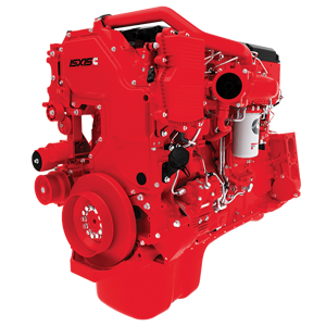
Explore Other Assets


© 2026 MaintainX. All rights reserved.