


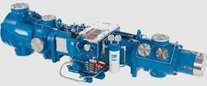
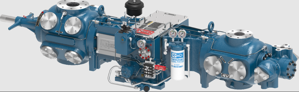
Ariel Heavy Duty Balanced Opposed Compressor JGN/1
Need answers fast?
Explore the manual using AI.

Turn manuals into instant answers
with your AI-powered assistantTurn manuals into instant answers
with your AI-powered assistant
Complete asset maintenance, one click away
Get instant access to all the maintenance information you need. Empower technicians to perform preventive maintenance with asset packages, ready to use right out of the box.

Documents & Manuals
Find all the essential guides in one place.
 Tensioning Guide
- Belt-diagram
- C-120 pulleys
+ 13 more

Work Order Templates
Pre-built workflows to keep your asset running smoothly.
- Daily Electrical System Inspection
- Replace Roller and Pulley
- Install Engine B-120
+ 29 more

Procedures
Integrate maintenance plans directly into your work orders.
- Motion Industries
- Applied Industrial Technologies
- Electrical Brothers
+ 5 more

Parts
Access the parts list for your equipment in MaintainX.
- Drive Motor
- B2 Rollers
- Tensioning System
+ 40 more
Ariel Heavy Duty Balanced Opposed Compressor JGN/1
Create an account to install this asset package.
Maintenance Plans for Ariel Heavy Duty Balanced Opposed Compressor Model JGN/1
Integrate maintenance plans directly into your work orders in MaintainX.
Piston Rod Pressure Packing Removal
CAUTION!: BE SURE THAT ALL PRESSURE IS RELIEVED FROM THE COMPRESSOR CYLINDERS PRIOR TO REMOVING PACKING.
Piston and piston rod removed
Packing diaphragm and oil wiper packing removed
All tubing connections from the top of the packing flange and the primary vent tube from the bottom of the flange disconnected
Twelve point cap screws that hold the pressure packing flange to the cylinder removed
At this point do not remove the small nuts from the studs. These studs hold the entire packing case together so it can be removed as an assembly.
Pressure packing removed into the crosshead guide
Pressure packing unstacked
Ring wear checked

Piston / Rod Removal
CAUTION: TO PREVENT PERSONAL INJURY, BE SURE THAT COMPRESSOR CRANKSHAFT CANNOT BE TURNED BY THE DRIVER OR COMPRESSOR CYLINDER GAS PRESSURE DURING MAINTENANCE
Engine-driven compressors: Is the center coupling removed or the flywheel locked?
Electric motor-driven compressors: Is the driver switch gear locked out during maintenance?
Is the system completely vented before performing any maintenance?
Before removing a cylinder head or VVCP, are all cap screws backed off 1/8 inch (3 mm)?
Is the head loose and the cylinder or VVCP completely vented?
Follow steps 1. through 5. at “Crosshead - Removal” on page 5-11.
With the cylinder head/unloader removed and the cross-head balance nut loosened, is the piston and rod assembly screwed out of the crosshead using the piston turning/piston nut torquing tool (Ariel furnished tool) and a speed wrench?
Is the crosshead nut turned off the piston rod?
Chain Idler Sprocket Replacement
Remove the frame top cover (or chain access cover for JGI). Remove the two cap screws that hold the eccentric adjustment cap to the end cover. Rotate the eccentric cap to loosen the chain. After dropping the chain off the idler sprocket, the entire assembly can be removed from the frame.
Remove the lock nut, cap screw, sprocket, Stat-O-Seal washer and the cap O-ring. Discard these items since they must be replaced with new parts.
Reassemble all parts using a new cap screw, Stat-O-Seal washer, sprocket, and lock nut. Tighten the idler lock nut to the recommended torque given in Table 1-12 on page 1-16.
Apply oil to and install a new O-ring on the eccentric adjustment cap.
Install the assembly and adjust the chain according to the instructions given in “Chain Adjustment” on page 5-24.
Sign off on the Chain Idler Sprocket Replacement
Main Bearings Removal
Warning: This procedure requires trained personnel with PPE!
DO NOT REUSE BEARING SHELLS. Determine bearing wear by checking actual jack and crankshaft thrust clearances against the clearance limits.
High copper content in the oil analysis may be an indication of main and/or connecting rod bearing wear, and/or chain idler, crosshead, connecting rod bushings wear.
There are notches in the frame and bearing cap for the bearing tabs in order to position and maintain the position of the bearing halves.
The old bearings halves are easily slid out, tab end first. New bearings are to be slid in (untabbed end first), and snapped into place.
On JGI models, remove the carrier bearing using a hydraulic press or jack. Remove the frame bearing using a hydraulic jack.
The new bushings are to be installed into the connecting rod by cooling the bushing in a 95 percent alcohol solution with dry ice solution.
CAUTION!: DO NOT TOUCH COLD SURFACES WITHOUT PROPER INSULATION TO PREVENT INJURY. ALCOHOL IS FLAMMABLE AND SHOULD ONLY BE USED IN OPEN AIR OR A WELL VENTILATED BUILDING.
NOTE: ABSOLUTE CLEANLINESS IS REQUIRED. ASSEMBLY MUST BE IMMEDIATE SO THAT THE BEARING DOES NOT WARM-UP AND STICK BEFORE IT IS IN PLACE.
1 Daily Compressor Maintenance
Warning: Ensure all power to the Unit is shut off and the Tank is drained of air pressure before servicing the Air Compressor.
After running a new compressor (or after a re-location, re-configuring or major overhaul) for the first 24 hours, shutdown, vent gas system and perform a hot alignment check at coupling within 30 minutes, while barring driver shaft to packager’s recommendations.
Realign if necessary to hold coupling hub face and rim hot alignment within 0.005 inch (0.13 mm) TIR, except for hub O.D. >17 in. (>43 cm) angular hub-face limit is increased to 0°1’ (0.0167°).
Check fastener torque on gas nozzle flange, valve cap, cylinder head, compressor rod; packing flange and, if applicable, crosshead guide to frame bolting.
If bearing temperatures increase or a visual inspection of the crankcase indicates bearing wear, check main, connecting rod and crankshaft-thrust bearing clearances.
Replace affected bearings if clearances are out of tolerances.
Check frame oil pressure. It should be 50 to 60 psig (3.5 to 4.2 barg) when at operating temperature.
Check frame oil level. It should be visible in the sight glass and approximately mid-level when running.
Check lubricator block cycle time.
Parts for Ariel Heavy Duty Balanced Opposed Compressor JGN/1
Access the parts list for your equipment in MaintainX.
Electronic Lubricator Fluid-Flow Monitor
A-11295
Battery Ariel
A-10807
Battery Radio Shack
960-0418
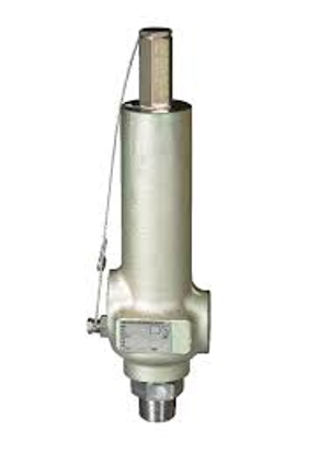
Balance Valve Internal Assembly With A Plug Assembly
A-10330
Valve Seal Repair Kit
A-8005-K
Electronic Lubricator Fluid-Flow Monitor
A-11295
Battery Ariel
A-10807
Battery Radio Shack
960-0418
Balance Valve Internal Assembly With A Plug Assembly
A-10330
Valve Seal Repair Kit
A-8005-K
Electronic Lubricator Fluid-Flow Monitor
A-11295
Battery Ariel
A-10807
Battery Radio Shack
960-0418
Balance Valve Internal Assembly With A Plug Assembly
A-10330
Valve Seal Repair Kit
A-8005-K
Unlock efficiency
with MaintainX CoPilot
MaintainX CoPilot is your expert colleague, on call 24/7, helping your team find the answers they need to keep equipment running.
Reduce Unplanned Downtime
Ensure your team follows consistent procedures to minimize equipment failures and costly delays.
Maximize Asset Availability
Keep your assets running longer and more reliably, with standardized maintenance workflows from OEM manuals.
Lower Maintenance Costs
Turn any technician into an expert to streamline operations, maintain more assets, and reduce overall costs.
Thousands of companies manage their assets with MaintainX

'%3e%3cpath%20fill='url(%23b)'%20d='M66.008%2080.068c-5.084-.786-9.763-3.834-12.442-8.68a16.942%2016.942%200%200%201-1.87-5.18c1.096.19%202.203.476%203.298.87%206.525%202.333%2010.836%207.68%2011.014%2012.99ZM51.47%2061.576c.488-5.524%203.62-10.716%208.847-13.597a17.132%2017.132%200%200%201%2011.335-1.882c-.798%208.145-7.43%2014.848-16.038%2015.599-1.417.119-2.799.07-4.144-.12Zm28.564-11.478a17.513%2017.513%200%200%201%203.727%204.62c4.608%208.335%201.584%2018.813-6.75%2023.409a16.988%2016.988%200%200%201-4.359%201.679%2019.624%2019.624%200%200%201-3.977-12.776c.346-7.561%204.942-13.931%2011.36-16.932Z'/%3e%3cpath%20fill='%23110F0D'%20fill-rule='evenodd'%20d='M142.831%2048.324h4.977V77.03h-4.977V48.324Zm27.278%2013.002c.322%201.048.453%202.263.453%203.62v12.073h-4.787V66.208c0-.75-.047-1.572-.154-2.143-.453-2.382-1.822-3.572-4.215-3.572-2.31%200-3.882%201.274-4.43%203.476-.143.596-.226%201.405-.226%202.25v10.8h-4.787V56.623h4.477v2.989c1.536-2.5%203.906-3.43%206.371-3.43%203.488%200%206.263%201.68%207.298%205.144Zm24.636%207.323c0%203.882-2.358%206.525-5.763%207.727-1.298.453-2.632.643-4.62.643h-10.169V48.324h9.085c1.691%200%203.156.143%204.049.38%203.465.93%205.727%203.68%205.727%207.335%200%202.441-.81%204.156-2.762%205.644%202.905%201.417%204.453%203.727%204.453%206.966Zm-15.634-8.656h4.584c1.024%200%201.917-.143%202.536-.417%201.215-.548%201.905-1.608%201.905-3.167%200-1.548-.643-2.572-1.845-3.132-.691-.31-1.762-.452-2.763-.452h-4.417v7.168Zm10.716%208.465c0-1.536-.893-3.37-3.227-3.893-.428-.095-1.036-.143-1.571-.143h-5.918v8.085h5.501c.56%200%201.429-.048%201.953-.167%201.94-.453%203.262-1.846%203.262-3.882Zm47.747-11.847-8.097%2020.408h-4.429l-8.109-20.408h5.191l5.192%2014.574%205.108-14.574h5.144Zm-20.218%2010.002c0%20.69-.036%201.262-.155%201.94h-15.943c.631%202.87%202.714%204.728%205.882%204.728%202.131%200%203.607-.882%204.703-2.525h4.87c-1.762%204.144-5.204%206.692-9.657%206.692-6.084%200-10.537-4.858-10.537-10.49%200-6.108%204.524-10.776%2010.335-10.776%206.239%200%2010.442%204.954%2010.502%2010.43Zm-4.763-1.405c-.333-2.846-2.643-4.858-5.691-4.858-2.894%200-5.287%201.929-5.621%204.858h11.312Zm-72.667%203.44c0%204.787-3.287%208.371-9.419%208.371H119.363V64.66c-1.917.274-3.87.69-5.811%201.238l4.537%2011.121h-5.418l-3.596-9.585c-5.144%202.084-10.085%205.216-14.217%209.585h-4.786L101.8%2048.312h4.56l5.68%2013.883a44.112%2044.112%200%200%201%207.323-1.774V48.312h9.084c1.703%200%203.156.143%204.061.393%203.453.929%205.727%203.667%205.727%207.323%200%201.917-.738%204.179-2.81%205.691%203.06%201.56%204.501%204.025%204.501%206.93Zm-15.634-8.667a62.664%2062.664%200%200%201%202.06-.036c1.703.012%203.239.131%204.608.37%201.441-.549%202.357-1.727%202.357-3.537%200-1.941-.881-3.144-2.488-3.667-.548-.18-1.358-.286-2.322-.286h-4.215v7.156Zm-16.55%203.905-3.715-9.894-6.394%2016.502c2.833-2.595%206.263-4.858%2010.109-6.608Zm27.254%204.74c0-2.775-3.131-4.347-8.513-4.418-.715%200-1.441.011-2.191.047v8.252h5.918c2.548%200%204.786-1.37%204.786-3.882Z'%20clip-rule='evenodd'/%3e%3c/g%3e%3cdefs%3e%3clinearGradient%20id='b'%20x1='51.47'%20x2='85.916'%20y1='62.946'%20y2='62.946'%20gradientUnits='userSpaceOnUse'%3e%3cstop%20stop-color='%23CD9F28'/%3e%3cstop%20offset='1'%20stop-color='%23ECD80B'/%3e%3c/linearGradient%3e%3cclipPath%20id='a'%3e%3cpath%20fill='%23fff'%20d='M51.47%2045.728h186.104V80.14H51.47z'/%3e%3c/clipPath%3e%3c/defs%3e%3c/svg%3e)


More from Ariel


Explore Other Assets


© 2026 MaintainX. All rights reserved.