


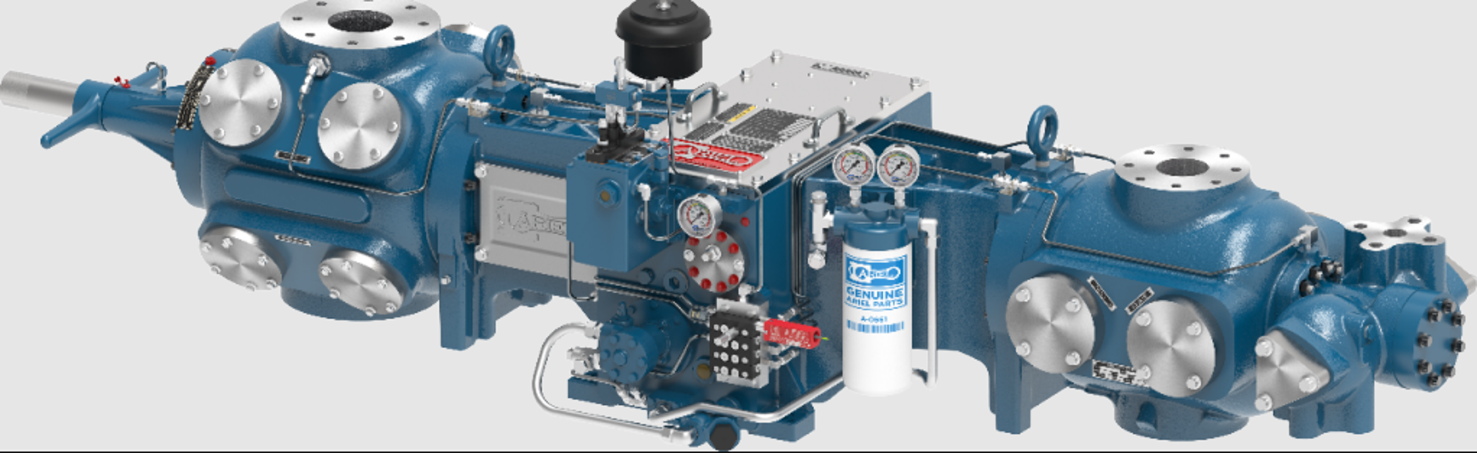
Ariel Heavy Duty Balanced Opposed Compressor JGM/2
Need answers fast?
Explore the manual using AI.
Turn manuals into instant answers
with your AI-powered assistantTurn manuals into instant answers
with your AI-powered assistant
Manual for Ariel Heavy Duty Balanced Opposed Compressor JGM/2
Complete asset maintenance, one click away
Get instant access to all the maintenance information you need. Empower technicians to perform preventive maintenance with asset packages, ready to use right out of the box.

Documents & Manuals
Find all the essential guides in one place.
 Tensioning Guide
- Belt-diagram
- C-120 pulleys
+ 13 more

Work Order Templates
Pre-built workflows to keep your asset running smoothly.
- Daily Electrical System Inspection
- Replace Roller and Pulley
- Install Engine B-120
+ 29 more

Procedures
Integrate maintenance plans directly into your work orders.
- Motion Industries
- Applied Industrial Technologies
- Electrical Brothers
+ 5 more

Parts
Access the parts list for your equipment in MaintainX.
- Drive Motor
- B2 Rollers
- Tensioning System
+ 40 more
Ariel Heavy Duty Balanced Opposed Compressor JGM/2
Create an account to install this asset package.
Maintenance Plans for Ariel Heavy Duty Balanced Opposed Compressor Model JGM/2
Integrate maintenance plans directly into your work orders in MaintainX.
Valves Maintenance
Warning: Refer to the correct valve assembly drawing and parts list and Hoerbiger's literature in the Ariel Parts Book before servicing any valve.
Valves have different springing for different pressure levels. The cylinder cover sheet in the Parts Book lists the valve originally supplied with each cylinder.
If different operating pressures are encountered, then different springs may be required.
Suction valve selected based on operating suction pressure?
Discharge valve selected based on operating discharge pressure?
Enter the operating speed (RPM)
Enter the gas specific gravity
Enter the suction temperature of the gas
Contact Ariel in Mount Vernon, for assistance in valve selection.

Lube Oil Pump Chain Sprocket Replacement
Remove the cap screws from the drive chain eccentric adjustment cap and rotate cap to loosen the chain
Remove all piping (tubing) from the pump
Remove fasteners from pump mounting adaptor
Remove the pump with sprocket
Measure the distance from the sprocket drive face to the pump mounting adaptor face
Remove the sprocket set screw from the oil pump
Pull the sprocket from the pump shaft
Remove the No. 204 Woodruff key
Re-assemble using a new gasket
Crosshead Removal
Caution: Ensure cylinders are completely vented before starting.
Cylinder heads loosened
Crosshead guide side covers removed
Cylinder head (or VVCP) removed
Crankshaft positioned to near its inner dead center position
Crosshead-balance nut set screws backed off
Crosshead-balance nut turned off the piston rod
Piston and rod assembly removed
Crankshaft positioned to near its outer dead center position
Piston Rod Pressure Packing Removal
CAUTION!: BE SURE THAT ALL PRESSURE IS RELIEVED FROM THE COMPRESSOR CYLINDERS PRIOR TO REMOVING PACKING.
Piston and piston rod removed
Packing diaphragm and oil wiper packing removed
All tubing connections from the top of the packing flange and the primary vent tube from the bottom of the flange disconnected
Twelve point cap screws that hold the pressure packing flange to the cylinder removed
At this point do not remove the small nuts from the studs. These studs hold the entire packing case together so it can be removed as an assembly.
Pressure packing removed into the crosshead guide
Pressure packing unstacked
Ring wear checked
Connecting Rod Removal
Remove the top cover from the crankcase (connecting rod and chain access covers on the JGI) and the side covers from the crosshead guides.
Remove the piston and piston rod as described in “Piston and Rod” on page 5-27.
Move the throw to near the outer dead center position.
Remove the crosshead as described in “Crosshead - Removal” on page 5-11, while supporting the connection rod so that it does not drop.
Turn the crankshaft until the throw is near to its highest point position. Completely loosen the connecting-rod-cap bolting and remove the top two capscrews.
Separate the rod cap from the rod. Use the bottom two rodcap capscrews as a handles to pull on the bottom of the rod cap while tapping the top face of the rod cap with a semi-soft faced hammer. Do not pull or strike the rod cap too hard; it may break the rod cap dowels. Work the rod cap away from rod as evenly as possible. Separating the two parts unevenly may break the rod cap dowels or cause them to bind in the rod dowel holes. See Figure above.
Remove the rod cap and its bearing half shell.
The bearing shell may fall out when separating the connecting rod and cap from the crankshaft pin. If bearing shells do not come loose, rotate/slide them out of the connecting rod and/or cap.
Turn the crankshaft throw to near the inner dead center position and remove the rod through the crosshead guide opening (or connecting rod access hole on the JGI).
Parts for Ariel Heavy Duty Balanced Opposed Compressor JGM/2
Access the parts list for your equipment in MaintainX.
Electronic Lubricator Fluid-Flow Monitor
A-11295
Battery Ariel
A-10807
Battery Radio Shack
960-0418
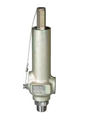
Balance Valve Internal Assembly With A Plug Assembly
A-10330
Valve Seal Repair Kit
A-8005-K
Electronic Lubricator Fluid-Flow Monitor
A-11295
Battery Ariel
A-10807
Battery Radio Shack
960-0418
Balance Valve Internal Assembly With A Plug Assembly
A-10330
Valve Seal Repair Kit
A-8005-K
Electronic Lubricator Fluid-Flow Monitor
A-11295
Battery Ariel
A-10807
Battery Radio Shack
960-0418
Balance Valve Internal Assembly With A Plug Assembly
A-10330
Valve Seal Repair Kit
A-8005-K
Unlock efficiency
with MaintainX CoPilot
MaintainX CoPilot is your expert colleague, on call 24/7, helping your team find the answers they need to keep equipment running.
Reduce Unplanned Downtime
Ensure your team follows consistent procedures to minimize equipment failures and costly delays.
Maximize Asset Availability
Keep your assets running longer and more reliably, with standardized maintenance workflows from OEM manuals.
Lower Maintenance Costs
Turn any technician into an expert to streamline operations, maintain more assets, and reduce overall costs.
Thousands of companies manage their assets with MaintainX

'%3e%3cpath%20fill='url(%23b)'%20d='M66.008%2080.068c-5.084-.786-9.763-3.834-12.442-8.68a16.942%2016.942%200%200%201-1.87-5.18c1.096.19%202.203.476%203.298.87%206.525%202.333%2010.836%207.68%2011.014%2012.99ZM51.47%2061.576c.488-5.524%203.62-10.716%208.847-13.597a17.132%2017.132%200%200%201%2011.335-1.882c-.798%208.145-7.43%2014.848-16.038%2015.599-1.417.119-2.799.07-4.144-.12Zm28.564-11.478a17.513%2017.513%200%200%201%203.727%204.62c4.608%208.335%201.584%2018.813-6.75%2023.409a16.988%2016.988%200%200%201-4.359%201.679%2019.624%2019.624%200%200%201-3.977-12.776c.346-7.561%204.942-13.931%2011.36-16.932Z'/%3e%3cpath%20fill='%23110F0D'%20fill-rule='evenodd'%20d='M142.831%2048.324h4.977V77.03h-4.977V48.324Zm27.278%2013.002c.322%201.048.453%202.263.453%203.62v12.073h-4.787V66.208c0-.75-.047-1.572-.154-2.143-.453-2.382-1.822-3.572-4.215-3.572-2.31%200-3.882%201.274-4.43%203.476-.143.596-.226%201.405-.226%202.25v10.8h-4.787V56.623h4.477v2.989c1.536-2.5%203.906-3.43%206.371-3.43%203.488%200%206.263%201.68%207.298%205.144Zm24.636%207.323c0%203.882-2.358%206.525-5.763%207.727-1.298.453-2.632.643-4.62.643h-10.169V48.324h9.085c1.691%200%203.156.143%204.049.38%203.465.93%205.727%203.68%205.727%207.335%200%202.441-.81%204.156-2.762%205.644%202.905%201.417%204.453%203.727%204.453%206.966Zm-15.634-8.656h4.584c1.024%200%201.917-.143%202.536-.417%201.215-.548%201.905-1.608%201.905-3.167%200-1.548-.643-2.572-1.845-3.132-.691-.31-1.762-.452-2.763-.452h-4.417v7.168Zm10.716%208.465c0-1.536-.893-3.37-3.227-3.893-.428-.095-1.036-.143-1.571-.143h-5.918v8.085h5.501c.56%200%201.429-.048%201.953-.167%201.94-.453%203.262-1.846%203.262-3.882Zm47.747-11.847-8.097%2020.408h-4.429l-8.109-20.408h5.191l5.192%2014.574%205.108-14.574h5.144Zm-20.218%2010.002c0%20.69-.036%201.262-.155%201.94h-15.943c.631%202.87%202.714%204.728%205.882%204.728%202.131%200%203.607-.882%204.703-2.525h4.87c-1.762%204.144-5.204%206.692-9.657%206.692-6.084%200-10.537-4.858-10.537-10.49%200-6.108%204.524-10.776%2010.335-10.776%206.239%200%2010.442%204.954%2010.502%2010.43Zm-4.763-1.405c-.333-2.846-2.643-4.858-5.691-4.858-2.894%200-5.287%201.929-5.621%204.858h11.312Zm-72.667%203.44c0%204.787-3.287%208.371-9.419%208.371H119.363V64.66c-1.917.274-3.87.69-5.811%201.238l4.537%2011.121h-5.418l-3.596-9.585c-5.144%202.084-10.085%205.216-14.217%209.585h-4.786L101.8%2048.312h4.56l5.68%2013.883a44.112%2044.112%200%200%201%207.323-1.774V48.312h9.084c1.703%200%203.156.143%204.061.393%203.453.929%205.727%203.667%205.727%207.323%200%201.917-.738%204.179-2.81%205.691%203.06%201.56%204.501%204.025%204.501%206.93Zm-15.634-8.667a62.664%2062.664%200%200%201%202.06-.036c1.703.012%203.239.131%204.608.37%201.441-.549%202.357-1.727%202.357-3.537%200-1.941-.881-3.144-2.488-3.667-.548-.18-1.358-.286-2.322-.286h-4.215v7.156Zm-16.55%203.905-3.715-9.894-6.394%2016.502c2.833-2.595%206.263-4.858%2010.109-6.608Zm27.254%204.74c0-2.775-3.131-4.347-8.513-4.418-.715%200-1.441.011-2.191.047v8.252h5.918c2.548%200%204.786-1.37%204.786-3.882Z'%20clip-rule='evenodd'/%3e%3c/g%3e%3cdefs%3e%3clinearGradient%20id='b'%20x1='51.47'%20x2='85.916'%20y1='62.946'%20y2='62.946'%20gradientUnits='userSpaceOnUse'%3e%3cstop%20stop-color='%23CD9F28'/%3e%3cstop%20offset='1'%20stop-color='%23ECD80B'/%3e%3c/linearGradient%3e%3cclipPath%20id='a'%3e%3cpath%20fill='%23fff'%20d='M51.47%2045.728h186.104V80.14H51.47z'/%3e%3c/clipPath%3e%3c/defs%3e%3c/svg%3e)


More from Ariel


Explore Other Assets


© 2026 MaintainX. All rights reserved.