


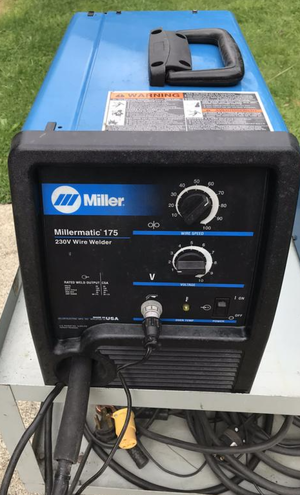
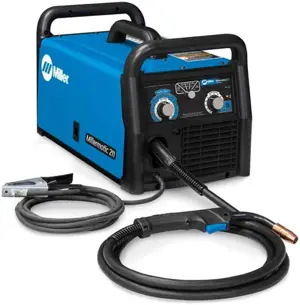
Miller Welding Machine Maxtron 450 CC/CV
Need answers fast?
Explore the manual using AI.
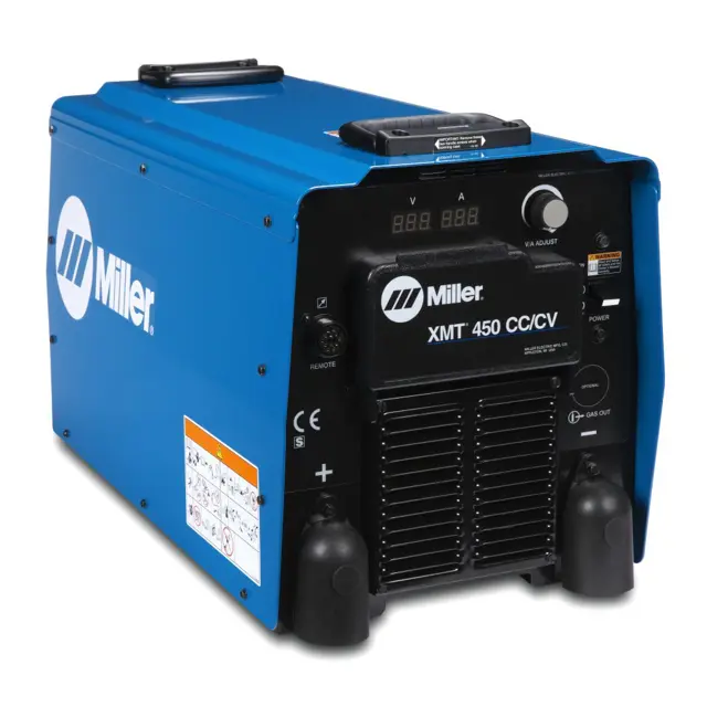
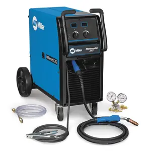
The Miller Welding Machine Maxtron 450 CC/CV is a versatile industrial welding machine designed for both constant current and constant voltage applications. Known for its reliability and performance, this model is ideal for a variety of welding tasks, making it a preferred choice among professionals in the welding industry.
Turn manuals into instant answers
with your AI-powered assistantTurn manuals into instant answers
with your AI-powered assistant
Manual for Miller Welding Machine Maxtron 450 CC/CV
Complete asset maintenance, one click away
Get instant access to all the maintenance information you need. Empower technicians to perform preventive maintenance with asset packages, ready to use right out of the box.

Documents & Manuals
Find all the essential guides in one place.
 Tensioning Guide
- Belt-diagram
- C-120 pulleys
+ 13 more

Work Order Templates
Pre-built workflows to keep your asset running smoothly.
- Daily Electrical System Inspection
- Replace Roller and Pulley
- Install Engine B-120
+ 29 more

Procedures
Integrate maintenance plans directly into your work orders.
- Motion Industries
- Applied Industrial Technologies
- Electrical Brothers
+ 5 more

Parts
Access the parts list for your equipment in MaintainX.
- Drive Motor
- B2 Rollers
- Tensioning System
+ 40 more
Miller Welding Machine Maxtron 450 CC/CV
Create an account to install this asset package.
Maintenance Plans for Miller Welding Machine Model Maxtron 450 CC/CV
Integrate maintenance plans directly into your work orders in MaintainX.
3 Monthly Welding Machine Maintenance
1. Replace Damaged Or Unreadable Labels.
2. Repair Or Replace Cracked Cables.
3. Replace Cracked Torch Body.
4. Repair Or Replace Cracked Cables And Cords.
5. Clean And Tighten Weld Terminals.
* Every 6 Months - Blow Out Or Vacuum Inside.;

Circuit Breakers And Fuses Maintenance
DANGER! Turn Off welding power source, disconnect input power, and check voltage on input capacitors.
1. Circuit Breaker CB1
• If CB1 opens, remote devices using 115 volts from Remote 14 receptacle stop. Manually reset CB1.
2. Circuit Breaker CB2
• If CB2 opens, remote devices using 24 volts from Remote 14 receptacle stop. Manually reset CB2.
3. Circuit Breaker CB3
• If CB3 opens, devices connected to the 715 volt dupiex receptacle and remote devices using 115 volts from Remote 14 receptacle stop. Manually reset CB3.
4. Fuse F1
• If F1 opens, the welding power source shuts down.
Optional Ground Current Sensor Maintenance
• Reed Relay (Ground Current Sensor - Optional)
1. Defects in external electrical circuitry may cause the ground wire to conduct welding current.
2. Relays CR1 and CR2 sense excessive current in the ground conductor and open the solid state contactor, shutting down weld output.
3. Open circuit voltage is not avail-able, but the fan motor FM runs and the pilot light PL1 stays on.
4. If the welding power source shuts down due to the ground current sensor, disconnect all power, and correct the problem before welding again.;
Input Capacitor Voltage Measurement
DANGER! Significant DC voltage can remain on capacitors after unit is Off. The input capacitor voltage can be measured across terminals on input rectifier SR1. Always check the voltage as shown to be sure the input capacitors have discharged before working on unit.
1. Tum Off welding power source, and disconnect input power.
2. Remove top cover.
• Input Rectifier SR1
• Voltmeter
3. Measure the DC voltage across the positive (+) and negative (-) terminals until voltage drops to near 0 (zero) volts.
4. Proceed with job inside unit.
5. Reinstall top cover when finished.;
Parts for Miller Welding Machine Maxtron 450 CC/CV
Access the parts list for your equipment in MaintainX.
Nut, BRS Hex 10-32
601835
Transducer, Current 300A
156313
Connector & Sockets, (Consisting Of)
153501
Connector, Rect Skt 22-18ga Amp 170362-3
147995
Fuse, Crtg 9A 500V Time Delay (230/460V)
148528
Nut, BRS Hex 10-32
601835
Transducer, Current 300A
156313
Connector & Sockets, (Consisting Of)
153501
Connector, Rect Skt 22-18ga Amp 170362-3
147995
Fuse, Crtg 9A 500V Time Delay (230/460V)
148528
Nut, BRS Hex 10-32
601835
Transducer, Current 300A
156313
Connector & Sockets, (Consisting Of)
153501
Connector, Rect Skt 22-18ga Amp 170362-3
147995
Fuse, Crtg 9A 500V Time Delay (230/460V)
148528
Unlock efficiency
with MaintainX CoPilot
MaintainX CoPilot is your expert colleague, on call 24/7, helping your team find the answers they need to keep equipment running.
Reduce Unplanned Downtime
Ensure your team follows consistent procedures to minimize equipment failures and costly delays.
Maximize Asset Availability
Keep your assets running longer and more reliably, with standardized maintenance workflows from OEM manuals.
Lower Maintenance Costs
Turn any technician into an expert to streamline operations, maintain more assets, and reduce overall costs.
Thousands of companies manage their assets with MaintainX

'%3e%3cpath%20fill='url(%23b)'%20d='M66.008%2080.068c-5.084-.786-9.763-3.834-12.442-8.68a16.942%2016.942%200%200%201-1.87-5.18c1.096.19%202.203.476%203.298.87%206.525%202.333%2010.836%207.68%2011.014%2012.99ZM51.47%2061.576c.488-5.524%203.62-10.716%208.847-13.597a17.132%2017.132%200%200%201%2011.335-1.882c-.798%208.145-7.43%2014.848-16.038%2015.599-1.417.119-2.799.07-4.144-.12Zm28.564-11.478a17.513%2017.513%200%200%201%203.727%204.62c4.608%208.335%201.584%2018.813-6.75%2023.409a16.988%2016.988%200%200%201-4.359%201.679%2019.624%2019.624%200%200%201-3.977-12.776c.346-7.561%204.942-13.931%2011.36-16.932Z'/%3e%3cpath%20fill='%23110F0D'%20fill-rule='evenodd'%20d='M142.831%2048.324h4.977V77.03h-4.977V48.324Zm27.278%2013.002c.322%201.048.453%202.263.453%203.62v12.073h-4.787V66.208c0-.75-.047-1.572-.154-2.143-.453-2.382-1.822-3.572-4.215-3.572-2.31%200-3.882%201.274-4.43%203.476-.143.596-.226%201.405-.226%202.25v10.8h-4.787V56.623h4.477v2.989c1.536-2.5%203.906-3.43%206.371-3.43%203.488%200%206.263%201.68%207.298%205.144Zm24.636%207.323c0%203.882-2.358%206.525-5.763%207.727-1.298.453-2.632.643-4.62.643h-10.169V48.324h9.085c1.691%200%203.156.143%204.049.38%203.465.93%205.727%203.68%205.727%207.335%200%202.441-.81%204.156-2.762%205.644%202.905%201.417%204.453%203.727%204.453%206.966Zm-15.634-8.656h4.584c1.024%200%201.917-.143%202.536-.417%201.215-.548%201.905-1.608%201.905-3.167%200-1.548-.643-2.572-1.845-3.132-.691-.31-1.762-.452-2.763-.452h-4.417v7.168Zm10.716%208.465c0-1.536-.893-3.37-3.227-3.893-.428-.095-1.036-.143-1.571-.143h-5.918v8.085h5.501c.56%200%201.429-.048%201.953-.167%201.94-.453%203.262-1.846%203.262-3.882Zm47.747-11.847-8.097%2020.408h-4.429l-8.109-20.408h5.191l5.192%2014.574%205.108-14.574h5.144Zm-20.218%2010.002c0%20.69-.036%201.262-.155%201.94h-15.943c.631%202.87%202.714%204.728%205.882%204.728%202.131%200%203.607-.882%204.703-2.525h4.87c-1.762%204.144-5.204%206.692-9.657%206.692-6.084%200-10.537-4.858-10.537-10.49%200-6.108%204.524-10.776%2010.335-10.776%206.239%200%2010.442%204.954%2010.502%2010.43Zm-4.763-1.405c-.333-2.846-2.643-4.858-5.691-4.858-2.894%200-5.287%201.929-5.621%204.858h11.312Zm-72.667%203.44c0%204.787-3.287%208.371-9.419%208.371H119.363V64.66c-1.917.274-3.87.69-5.811%201.238l4.537%2011.121h-5.418l-3.596-9.585c-5.144%202.084-10.085%205.216-14.217%209.585h-4.786L101.8%2048.312h4.56l5.68%2013.883a44.112%2044.112%200%200%201%207.323-1.774V48.312h9.084c1.703%200%203.156.143%204.061.393%203.453.929%205.727%203.667%205.727%207.323%200%201.917-.738%204.179-2.81%205.691%203.06%201.56%204.501%204.025%204.501%206.93Zm-15.634-8.667a62.664%2062.664%200%200%201%202.06-.036c1.703.012%203.239.131%204.608.37%201.441-.549%202.357-1.727%202.357-3.537%200-1.941-.881-3.144-2.488-3.667-.548-.18-1.358-.286-2.322-.286h-4.215v7.156Zm-16.55%203.905-3.715-9.894-6.394%2016.502c2.833-2.595%206.263-4.858%2010.109-6.608Zm27.254%204.74c0-2.775-3.131-4.347-8.513-4.418-.715%200-1.441.011-2.191.047v8.252h5.918c2.548%200%204.786-1.37%204.786-3.882Z'%20clip-rule='evenodd'/%3e%3c/g%3e%3cdefs%3e%3clinearGradient%20id='b'%20x1='51.47'%20x2='85.916'%20y1='62.946'%20y2='62.946'%20gradientUnits='userSpaceOnUse'%3e%3cstop%20stop-color='%23CD9F28'/%3e%3cstop%20offset='1'%20stop-color='%23ECD80B'/%3e%3c/linearGradient%3e%3cclipPath%20id='a'%3e%3cpath%20fill='%23fff'%20d='M51.47%2045.728h186.104V80.14H51.47z'/%3e%3c/clipPath%3e%3c/defs%3e%3c/svg%3e)


More from Miller


Explore Other Assets


© 2026 MaintainX. All rights reserved.